In my experience designing inertial systems for field operations, engineers often overlook one deceptively simple number: Angle Random Walk. It’s not as flashy as bias stability or bandwidth, but it defines the real-world ceiling of how long your system can stay trusted—especially when GNSS drops out. ARW isn’t an error you calibrate out. It’s the noise that keeps growing, second by second. Once you understand how it works, it changes how you evaluate every IMU on your bench.
ARW isn’t a spec—it’s a clock. From the moment your IMU starts, it tells you how fast orientation trust degrades. The lower it is, the longer your system stays right.
Over the years, I’ve seen teams select IMUs based on bias specs and bandwidth charts, only to run into drift that defies simulation. That drift often isn’t from what they missed—it’s from what they didn’t weigh heavily enough: ARW. Once you realize ARW defines your noise horizon, you start reading datasheets differently. You stop asking “What’s the precision?” and start asking “How long can I rely on this thing before uncertainty takes over?”
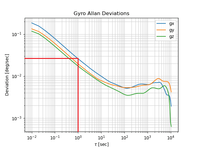
Table of contents
What Exactly Is Angle Random Walk (ARW)?
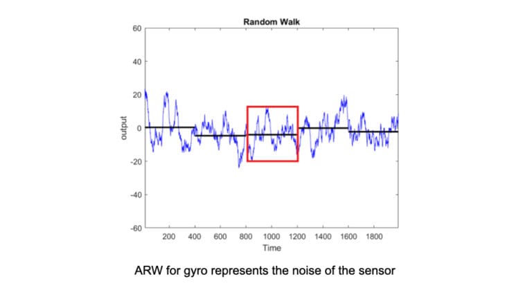
In simple terms, Angle Random Walk (ARW) is the noise your gyroscope accumulates the moment you start integrating angular rate. But let’s be clear—this isn’t measurement error or bias drift. ARW is the square-root-of-time growth in uncertainty that emerges from white noise in the gyro’s signal path. You can’t calibrate it out, and you can’t wait for it to stabilize—it’s always there, ticking in the background.
I often describe ARW to junior engineers as the “baseline blur” of your orientation estimate. It doesn’t care if your platform is moving or still. Even in a lab, with a rock-steady sensor bolted to the table, ARW adds up. That’s what makes it so fundamental. It’s not a performance flaw—it’s physics.
How Is ARW Measured in Practice?
The gold standard for measuring ARW is Allan variance analysis.
This technique decomposes different types of noise over varying time intervals. At short averaging durations, ARW reveals itself as a characteristic -½ slope on a log-log Allan deviation plot. It’s the signature of white noise in your gyro’s output, and it sets the floor for your attitude accuracy.
But you can’t just trust the datasheet.
In my workflow, I always run controlled static tests on a mechanically isolated platform, log the raw gyro data, and generate my own Allan plots. A clean short-time slope tells me the gyro is stable. If the slope is noisy or irregular, I know that what’s advertised as “0.05°/√h” might not hold in deployment.
ARW is not just a number—it’s a pattern you should see in real data.
That’s why I treat ARW as something to validate, not just to quote. If your Allan variance doesn’t agree with the spec, your entire fusion stack could suffer the consequences later.
Why Is ARW Critical for IMU Accuracy?
Noise That Never Sleeps
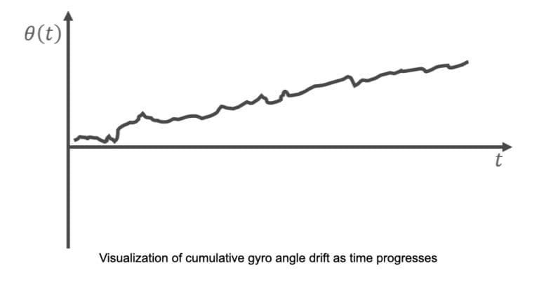
Unlike deterministic errors like bias or scale factor, ARW continuously injects uncertainty into your orientation estimate. Because gyroscopes measure angular rate, and those rates are integrated over time, even small random fluctuations compound into significant angle drift. You don’t need minutes or hours to feel its effect—on high-sensitivity platforms, ARW starts degrading accuracy within seconds.
The Invisible Ceiling of Navigation
ARW sets a hard limit on how long your IMU can provide reliable orientation when external corrections (like GNSS or magnetometers) are unavailable. I’ve seen perfectly tuned Kalman filters gradually lose grip on heading simply because the underlying gyro had an ARW too high for the mission duration. This isn’t a software problem—it’s a physics constraint. In every inertial system I’ve designed, once I know the ARW, I can predict when navigation will fail. And that’s powerful.
How Does ARW Differ from Bias Instability?
| Angle Random Walk (ARW) | Bias Instability |
|---|---|
| Short-term noise. Appears instantly in gyro output as small random fluctuations. | Mid- to long-term drift. A slow wandering of the zero-rate level over time. |
| Increases with √time. Causes orientation error to accumulate continuously. | Has a flat plateau in Allan variance plots—it’s the “hump” engineers look for. |
| Unpredictable but bounded. Can be modeled statistically, but not removed. | Slowly varying. Often modeled and partially compensated with filters. |
| Dominates short-duration accuracy. Especially critical in fast-moving, high-dynamic systems. | Dominates long-term precision. Matters in applications like survey-grade INS or long-endurance navigation. |
Why the confusion?
Because both ARW and bias instability cause drift—but in different ways and at different timescales. Engineers new to inertial systems often conflate them, thinking bias drift is the only source of navigation error. In my experience, it’s often ARW that limits performance in tactical missions, especially where operating time without GNSS is measured in minutes, not hours.
What Are Typical ARW Values for Different IMUs?
In real projects, I rarely ask “what’s the best IMU?”—I ask, “what’s the lowest ARW I can get within this size, weight, and budget?” ARW is often the spec that quietly tells you whether a sensor is consumer-grade, tactical-grade, or strategic.
Here’s how I’ve seen ARW break down across sensor classes:
| IMU Class | Typical ARW (°/√h) | Where It Belongs |
|---|---|---|
| Consumer MEMS | 1 – 10 | Phones, wearables, entry-level robotics |
| Industrial MEMS | 0.1 – 1 | Drones with GNSS, light autonomous platforms |
| Tactical MEMS | 0.05 – 0.1 | Defense UAVs, weapon stabilization, vehicles |
| Navigation-grade FOG | 0.001 – 0.01 | Maritime, aerospace, rail, long-endurance UAVs |
| Strategic RLG | < 0.001 | Submarines, ICBMs, high-security military systems |
I treat ARW like a cut-off filter in design decisions.
If my system needs to survive 30 minutes without GNSS and hold 1° heading accuracy, then MEMS units with 0.2°/√h simply won’t cut it. Tactical MEMS might barely manage. If I need performance beyond that, it’s FOG or nothing.
What Comes Next?
By now, you should have a clear understanding of what ARW is, how it’s measured, and why it matters. But theory is only half the equation. In the second part of this series, I’ll walk through how ARW manifests in real systems—from UAV drift to inertial-only missions—and how engineers like us design around it. We’ll get tactical: software limitations, mechanical isolation, fusion strategies, and hard ARW thresholds for critical applications.
→ Continue to Part 2: Designing with ARW in Mind