Even the most precise fiber optic gyroscopes face a hidden enemy: temperature. From arctic cold to desert heat, thermal drift alters bias, scale factor, and noise. Without smart design, small errors accumulate into mission-critical failures. This article explains why temperature matters and how advanced strategies ensure FOG reliability in extreme environments.
Thermal sensitivity in fiber optic gyroscopes arises from material expansion, refractive index shifts, and optical source behavior. Advanced strategies–thermal compensation, coil winding optimization, and robust calibration–enable FOGs to sustain accuracy in extreme environments.
Temperature drift isn’t just a datasheet figure—it determines whether a gyroscope can operate reliably in submarines, UAVs, or spacecraft. In fiber optic gyroscopes, thermal effects directly influence bias stability and accuracy. The following sections outline the key sensitivities and the engineering strategies that ensure dependable performance in extreme environments.
Table of contents
What Makes Thermal Sensitivity a Critical Factor in FOGs?
Thermal sensitivity is often underestimated, but in fiber optic gyroscopes it directly dictates long-term reliability.
FOGs measure rotation using the Sagnac effect, where phase differences accumulate over kilometers of optical fiber. This extreme precision also makes them vulnerable to even minor temperature variations, which can disrupt multiple subsystems at once.
Key factors influencing thermal sensitivity include:
Fiber Coil Effects – thermal expansion, refractive index shifts, and micro-bending stresses alter the optical path length, introducing phase errors.
Optical Source Behavior – wavelength drift and power fluctuations with temperature destabilize the interference pattern.
Detector Response – dark current growth and responsivity changes increase noise and reduce signal integrity.
When combined, these effects can degrade bias stability, scale factor linearity, and ARW, pushing a tactical-grade FOG toward commercial-level performance if not controlled. This is why thermal resilience is considered the most critical design challenge in field-ready fiber optic gyroscopes.
How Temperature Affects the Fiber Coil and Refractive Index
The fiber coil is the FOG’s core, and its optical path length is highly vulnerable to heat.
Temperature alters the coil in multiple ways: expansion changes its physical length, refractive index shifts alter light velocity, and uneven gradients induce micro-bending stresses. Each mechanism introduces phase errors that grow with coil length.
| Thermal Effect | Cause | Impact on FOG Accuracy |
|---|---|---|
| Expansion | Fiber length increases with temperature | Alters effective optical path, distorting scale factor |
| Refractive Index Shift | Thermo-optic coefficient of silica changes | Introduces phase errors |
| Micro-bending | Uneven heating induces stress | Creates additional bias drift |
For long coils—often 5 to 20 km in tactical FOGs—even microscopic dimensional changes can magnify into significant navigation errors. A few millimeters of path length variation are enough to alter bias stability by degrees per hour, making coil design and material selection a defining factor in FOG reliability.
How the Optical Source and Detectors Respond to Temperature
Beyond the fiber coil, the optical source and detectors introduce their own temperature sensitivities.
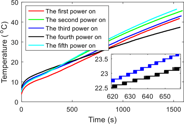
The light source—often a laser diode or superluminescent diode (SLD)—is highly dependent on temperature. As heat changes, wavelength drifts by 0.1–0.3 nm/°C, directly affecting interference accuracy. Output power also fluctuates, raising the system’s noise floor.
Photodetectors face similar challenges:
- Dark currentroughly doubles every 10°C, introducing additional noise.
- Responsivitychanges with temperature, lowering signal-to-noise ratio.
- Linearitymay degrade, distorting measurement accuracy under rapid fluctuations.
To stabilize the optical chain, advanced FOGs integrate:
- Thermoelectric coolers (TECs)to regulate source temperature.
- Low-drift photodiodesdesigned for wide thermal ranges.
- Feedback control loopsthat actively compensate intensity and wavelength changes.
These measures ensure the FOG maintains signal stability from -40°C to +85°C, preventing optical chain drift from compromising navigation accuracy.
Impact on Bias Stability and Angle Random Walk (ARW)
Bias stability and ARW are the ultimate measures of FOG quality, both strongly affected by temperature.
Bias instability represents slow drift over time, while ARW defines short-term noise. Thermal fluctuations can degrade both simultaneously:
Bias Instability
- Uneven coil expansion under thermal gradients → slow bias drift
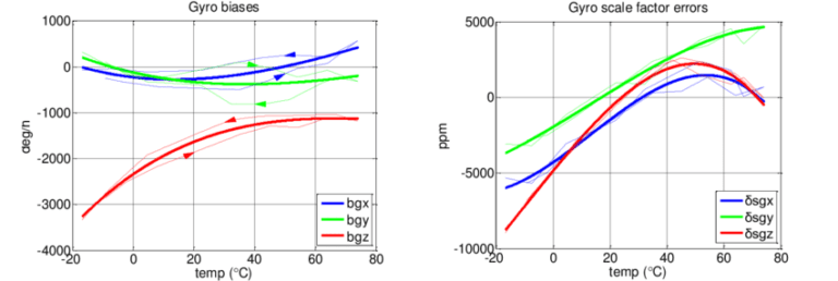
- In poor designs, drift can exceed 1 °/h, far beyond tactical-grade limits
- Defense-grade FOGs target ≤0.05 °/hstability
Angle Random Walk (ARW)
- Noise increases as optical sources and electronics lose thermal stability
- High ARW values degrade orientation precision over short intervals
- Stabilized sources and compensation circuits can cut ARW by 30%+
When bias stability and ARW deteriorate, tactical FOGs may perform no better than commercial sensors. Maintaining tight control over these parameters is therefore the cornerstone of designing mission-ready gyroscopes.
Coil Winding Techniques to Minimize Temperature Drift
How a fiber coil is wound often decides whether a FOG drifts The way a fiber coil is wound determines whether thermal effects cancel or accumulate.
A fiber coil is not just a spool of glass—it is a precisely engineered structure where geometry, tension, and symmetry define long-term stability. Improper winding amplifies thermal gradients, while optimized patterns can suppress drift by orders of magnitude.
Key strategies include:
- Quadrupole Winding– uses a geometric pattern to cancel non-reciprocal thermal expansion effects.
- Symmetric Layering– ensures temperature stress is evenly distributed across the coil.
- Controlled Tension– prevents micro-bending from fiber strain during thermal cycling.
- Low-Shrinkage Adhesives– reduce creep and stress relaxation over repeated cycles.
Reference Case: A 5 km fiber coil with uncontrolled winding showed bias drift exceeding 2 °/h under thermal swings, while precision quadrupole winding reduced it below 0.05 °/h—a 40× improvement.
Material Choices for Extreme-Environment FOGs
Hardware alone cannot eliminate thermal drift—electronics and algorithms complete the defense.
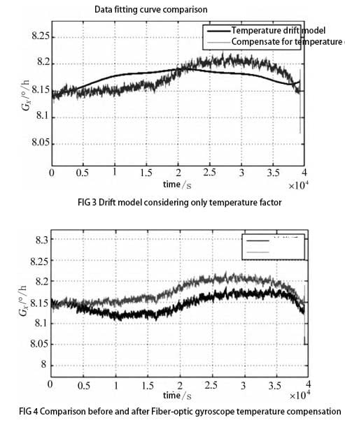
Modern FOGs embed intelligent electronics to sense, model, and correct thermal effects in real time. Compensation strategies can be grouped as follows:
| Compensation Method | How It Works | Contribution to Stability |
|---|---|---|
| Temperature Sensors | Placed near fiber coil and optical source to capture gradients | Provide raw data for correction models |
| Correction Models | Firmware uses pre-characterized temperature-error tables | Eliminates predictable drift patterns |
| Adaptive Signal Processing | Real-time algorithms refine bias and noise suppression | Handles residual and dynamic thermal errors |
Technical Note: Hardware design may reduce 70–80% of thermal drift, but the final 20–30% is controlled through electronics and signal processing. This layered approach ensures that tactical-grade FOGs remain stable across rapid temperature transitions and long-duration missions.
Electronics and Signal Processing Compensation Methods
Hardware alone cannot defeat thermal drift—electronics and algorithms are essential allies.
Modern FOGs embed intelligent electronics that sense and compensate thermal effects in real time:
- Temperature Sensorsplaced near the fiber coil and light source.
- Correction Modelsembedded in firmware to map thermal errors.
- Adaptive Signal Processingthat continuously adjusts filtering.
Hybrid defense: mechanical design eliminates 70–80% of thermal sensitivity, while electronics/software compensate the remainder, ensuring stable performance across full mission profiles.
Calibration Strategies: Factory vs. In-Field Compensation
Calibration transforms raw hardware into a field-ready sensor resilient against thermal drift.
Two major strategies exist:
| Calibration Type | Method | Advantage | Limitation |
|---|---|---|---|
| Factory Calibration | Chamber cycling, error mapping | Stable & predictable | May not reflect field conditions |
| In-Field Calibration | Adaptive learning during missions | Real-condition accuracy | Computationally heavy |
Modern FOGs often combine both: factory baselines plus in-field adaptation, ensuring long-term resilience even under unique mission conditions.
Design Lessons from Defense and Aerospace Applications
Decades of deployment in demanding environments have shaped how FOGs are built today.
Different platforms impose unique challenges:
- Submarines:Require absolute stability over months of continuous operation.
- UAVs:Need lightweight yet robust FOGs for rapid altitude transitions.
- Satellites:Face wide performance demands including precision and resilience in space.
The universal lesson is that no single technique is enough. Success comes from integrating winding, materials, optics, electronics, and calibration into one coherent design.
Building on these lessons, GuideNav has spent over a decade refining FOG technology—continuously innovating, optimizing precision, and validating through extreme-condition tests. This commitment ensures that our solutions meet the rising accuracy demands of defense and aerospace clients worldwide.
