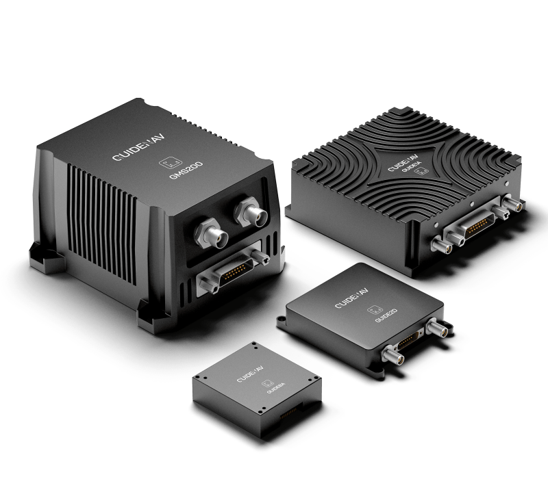
GUIdenav's cutting edge ins solutions for all
Inertial Navigation System (INS)
15,000+ Systems in Operation in 35+ Countries
Custom Solutions Trusted by Global Key Players
GuideNav provides comprehensive INS solutions, incorporating both MEMS and Fiber Optic Gyroscope (FOG) technologies. Our INS systems are engineered to deliver exceptional accuracy and reliability, catering to a broad spectrum of applications. Whether you need the compact and cost-effective advantages of MEMS or the unparalleled precision of FOG, our solutions ensure precise position, velocity, and orientation data, even in the most challenging environments.
Introducing our mems inertial measurement system products
Our Featured MEMS INS
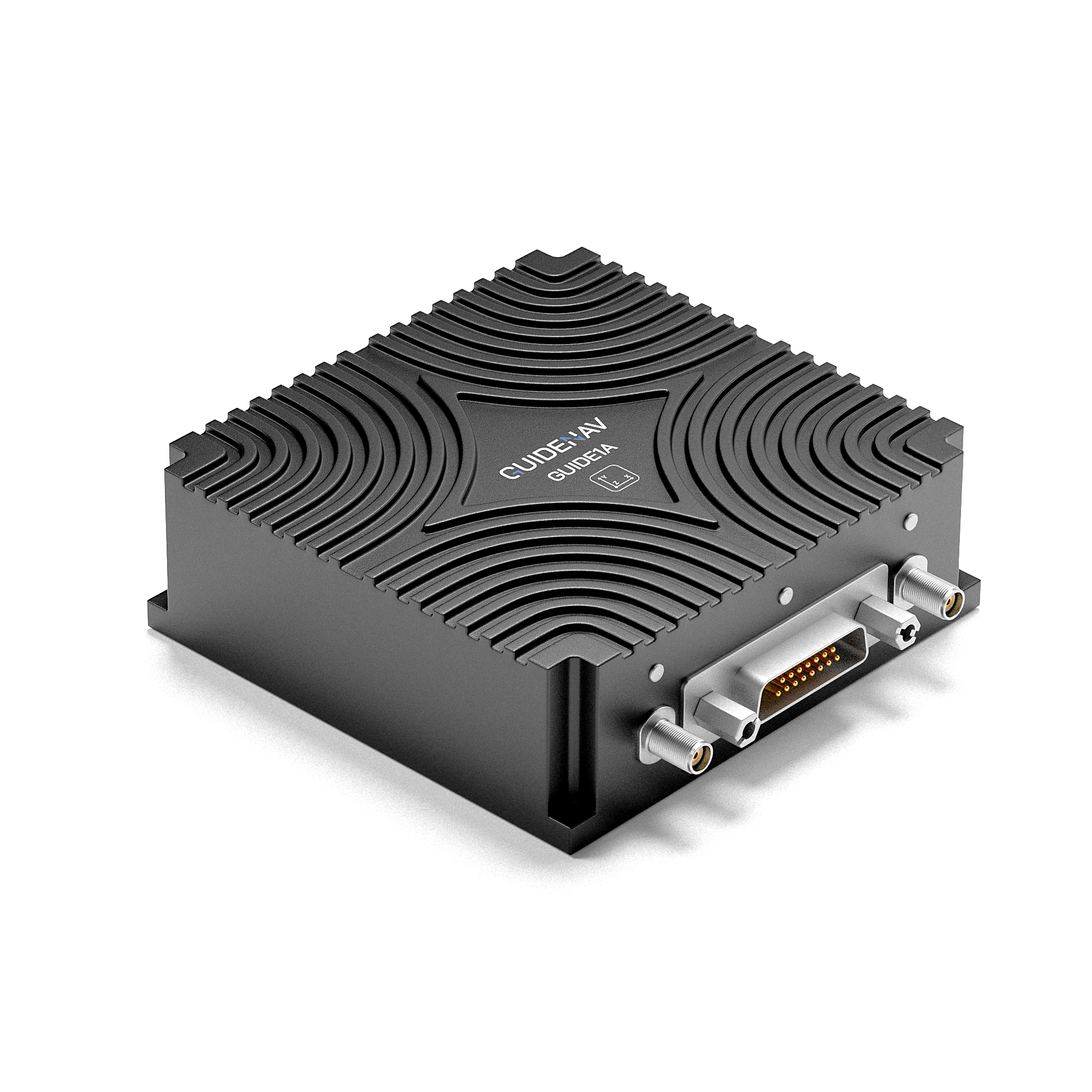
- GNSS-aided inertial navigation
- Cost-effective
- Attitude accuracy: 0.1°
- heading accuracy: 0.1°
- For Industrial & Automotive
- Customized solution available
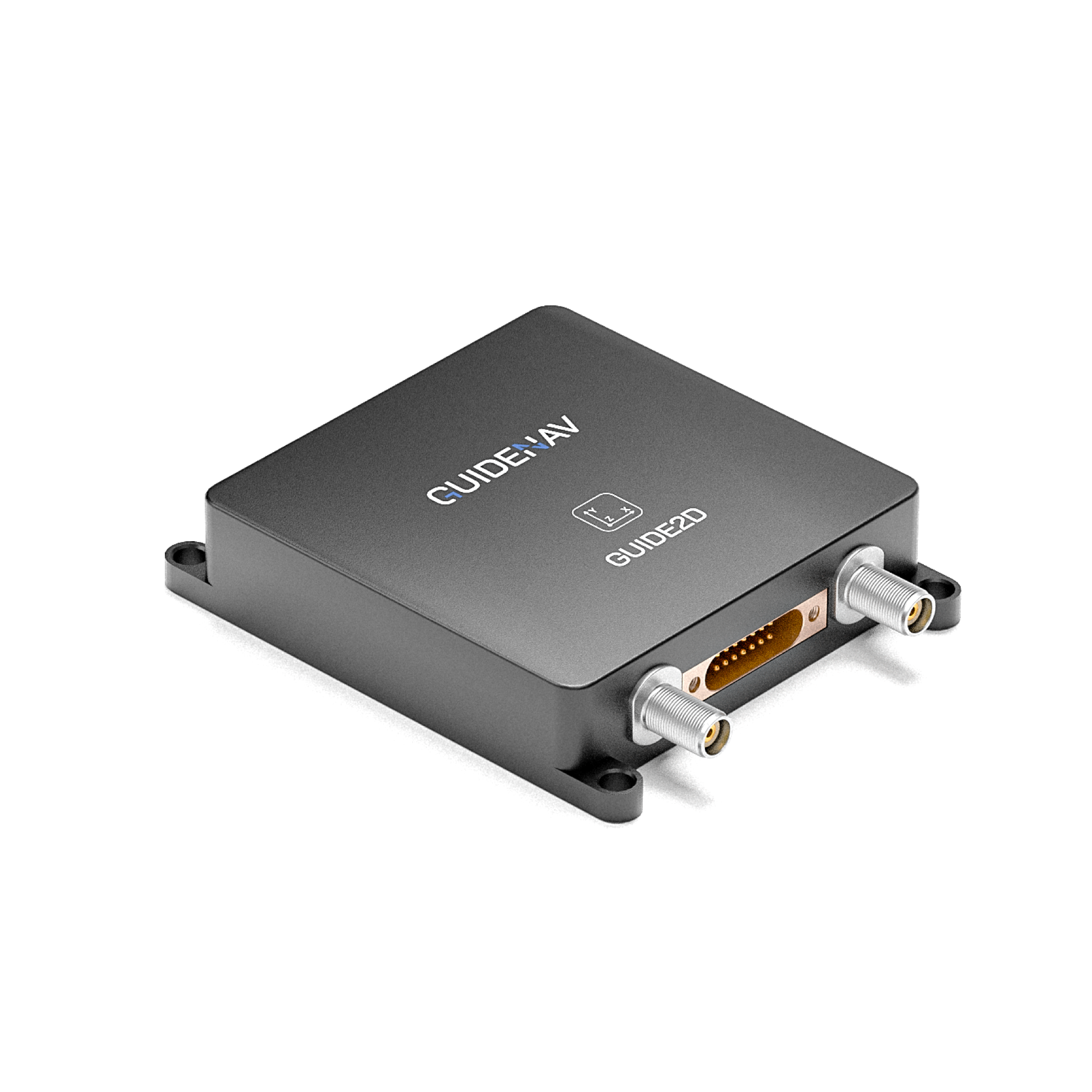
- GNSS-aided inertial navigation
- Attitude accuracy: 0.1°
- heading accuracy: 0.1°
- Optimized sWaP-C (Size, Weight and Power – Cost)
- For military & commercial aircrafts
- Customized solution available
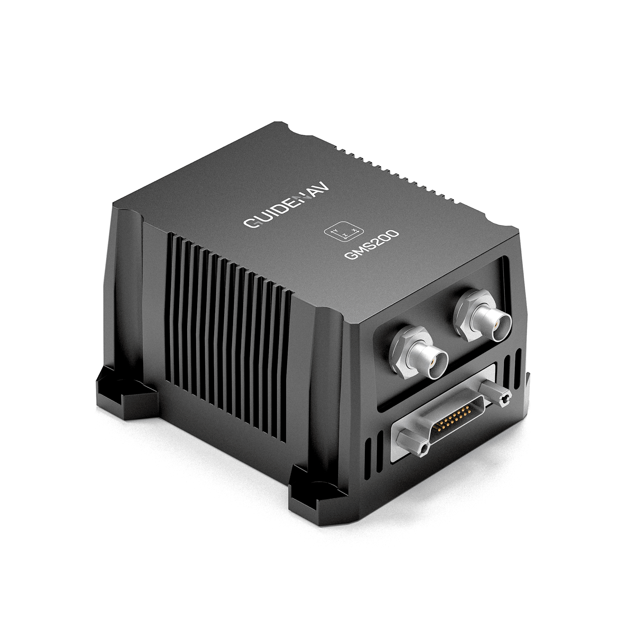
- High-precision
- Dual-antenna Fast Orientation
- Attitude accuracy: 0.1°
- heading accuracy: 0.05°
- Optimized design of antenna shielding
- Customized solution available
Introducing our Fiber optic inertial measurement system products
Our Featured FOG INS
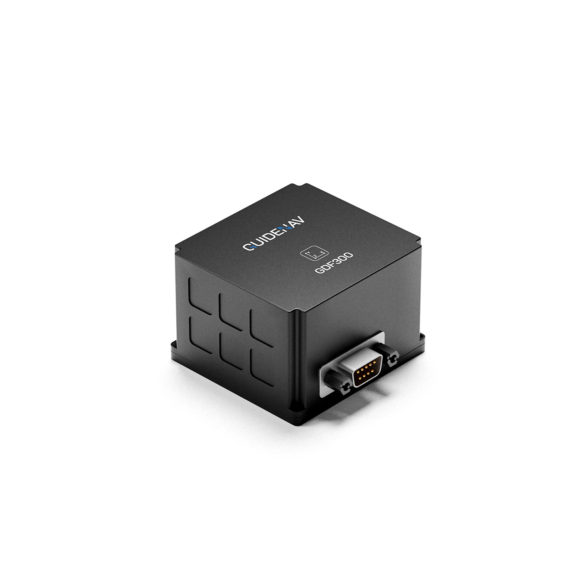
- GNSS-aided inertial navigation
- Enhanced Kalman Filter Algorithm
- Roll &Pitch accuracy: 0.01° (RMS) (static dual antenna, 2m baseline)
- Heading Accuracy : 0.05°(RMS)
- Gyroscope Bias Stability: ≤0.15°/h(1σ,10s Mean-Smooth )

- GNSS-aided inertial navigation
- Enhanced Kalman Filter Algorithm
- Roll &Pitch accuracy: 0.005° (RMS) (static dual antenna, 2m baseline)
- Heading Accuracy : 0.02°(RMS)
- Gyroscope Bias Stability: ≤0.02°/h(1σ,10s Mean-Smooth )
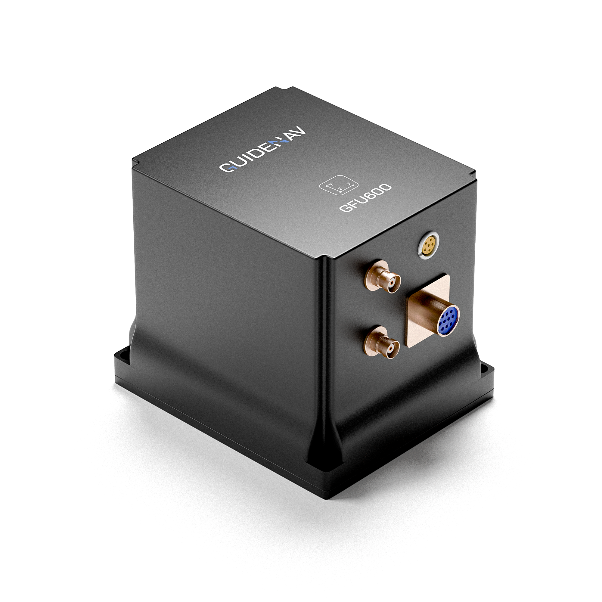
- GNSS-aided inertial navigation
- Enhanced Kalman Filter Algorithm
- Roll &Pitch accuracy: 0.005° (RMS) (static dual antenna, 2m baseline)
- Heading Accuracy : 0.015°(RMS)
- Gyroscope Bias Stability: ≤0.006°/h(1σ,10s Mean-Smooth )
Get Your Custom Solution Now
Your project deserves a solution tailored to your exact specifications. To ensure we provide the best Inertial Navigation System (INS) for your needs, we invite you to share the specific parameters and performance requirements of your applications. Whether it’s precision, stability, or size constraints, our team is ready to help you find the perfect fit.
Table of Contents
Download this page as a PDF
To save you time, we have also prepared a PDF version containing all the contents of this page, only leave your email and you will get the download link immediately.

Introducing Inertial Navigation System
What is an Inertial Navigation System (INS)?
An Inertial Navigation System (INS) is a precision system that calculates an object’s position, orientation, and velocity using accelerometers and gyroscopes. Unlike GPS, an INS operates independently of external signals, making it essential for navigation in areas where GPS is unreliable or unavailable, such as underwater or in space.
INS uses gyroscopes to track rotation and accelerometers to measure linear movement. By continuously processing this data, the system accurately determines the object’s current position and orientation through dead reckoning.
INS is crucial for high-precision navigation in aerospace, defense, marine, and autonomous systems, ensuring reliable performance even in the most challenging environments.
Key Features of guidenav's Inertial navigation systems
Key Features of INS
Autonomous Navigation
Feature
INS operates independently without relying on external signals like GPS, providing accurate navigation even in signal-deprived environments.
Advantage
Ensures continued navigation capability in scenarios where GPS is unavailable or compromised, such as underground, underwater, or in combat zones.
High Precision and Low Drift
Feature
INS offers extremely high accuracy, particularly with systems using FOG (Fiber Optic Gyroscopes), characterized by low drift and long-term stability.
Advantage
Maintains accuracy over long durations, essential for high-precision applications like aerospace, marine navigation, and military missile guidance.
Rapid Response and Real-Time Performance
Feature
INS provides quick responses to dynamic changes, delivering real-time data on attitude, velocity, and position.
Advantage
Crucial for high-dynamic environments, such as drone flight control and precision machinery operation, where real-time accuracy is vital.
Robustness and Durability
Feature
INS is designed to be robust, capable of withstanding harsh environmental conditions, including extreme temperatures, vibrations, and shocks.
Advantage
Essential for missions in extreme conditions, such as military operations, industrial applications, and deep-sea exploration, ensuring system reliability and durability.
Key Features of guidenav's mems gyroscope
What is the difference between GPS and Inertial Navigation System?
Signal Dependency
GPS
Relies on satellite signals to provide position data, making it highly effective in open outdoor environments. However, in environments where signals are obstructed (e.g., tunnels, forests, underground), or where signals are intentionally jammed or blocked, GPS may fail or its accuracy may degrade significantly.
INS
Operates independently of external signals, providing position and motion information based on internal sensors. INS remains reliable not only in GPS-denied environments (e.g., underwater, underground, space) but also when GPS signals are intentionally jammed or blocked, offering continuous and uninterrupted navigation information.
Accuracy and Stability
GPS
When satellite signals are strong and unobstructed, GPS offers high-precision absolute positioning. However, it is susceptible to signal interference, jamming, or multipath effects, leading to potential fluctuations in accuracy.
INS
Provides very high accuracy and stable attitude information over short periods. INS is crucial for maintaining accurate navigation when GPS signals are unavailable or unreliable.
Usage Scenarios
GPS
Ideal for applications requiring absolute position, such as car navigation, smartphone location services, and outdoor activities. It’s widely used for navigation tasks in open environments where signal integrity is assured.
INS
Essential in scenarios requiring uninterrupted navigation when GPS is unavailable, unreliable, or actively blocked—such as in military operations, aircraft, submarines, drones, and missile guidance. INS provides continuous motion information, ensuring reliability in complex or constrained environments.
Initial Setup and Calibration
GPS
Requires time to lock onto satellite signals (especially during a cold start) before providing accurate initial positioning. Its reliance on signal acquisition makes it vulnerable to delays in challenging environments.
INS
Once initialized, INS provides immediate motion and position data without the need for external signal acquisition. This makes INS invaluable in situations where speed and continuity are critical, and periodic calibration ensures its ongoing accuracy.
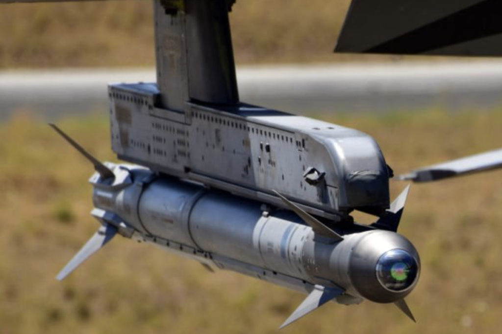

MEMS Gyroscope
What is the difference between IMU and Inertial Navigation System?
An IMU (Inertial Measurement Unit) provides the raw data on acceleration and angular velocity, and sometimes magnetic fields, which reflect an object’s motion and orientation. To form an INS (Inertial Navigation System), an IMU is combined with a processing unit that integrates this raw data over time to calculate and continuously update the object’s position, velocity, and orientation. Essentially, an INS is an IMU plus the necessary algorithms and processing power to transform the IMU’s sensor data into a full navigation solution.
When an IMU is integrated into an INS, the system is used in advanced applications such as aircraft, submarines, spacecraft, and autonomous vehicles, where precise, continuous navigation and real-time position tracking are critical. The INS leverages the IMU’s data to deliver comprehensive navigation solutions in environments where accuracy and reliability are paramount.
A Step by step guide to select you the right INS model for your dedicated applications
How to Select the Right Inertial Navigation System Model
STEP 1
Define Application and Requirements
Identify the specific application for the INS and define the key specs such as required accuracy, drift rate, and response time.
Guidance: High-precision, low-drift applications are better suited for FOG INS; medium-precision, cost-sensitive applications may consider MEMS INS.
STEP 2
Assess Size and Weight Constraints
Evaluate the system’s size and weight requirements, particularly in space-constrained or portable devices.
Guidance: If size and weight are critical factors, MEMS INS is preferable due to its compact and lightweight design.
STEP 3
Analyze Power Consumption Needs
Determine the power consumption requirements, especially for battery-powered or power-sensitive applications.
Guidance: For low-power applications, MEMS INS is the preferred choice; for applications where power consumption is less of a concern but high performance is needed, FOG INS may be more suitable.
STEP 4
Consider Budget Constraints
Assess the project budget in relation to the performance needs of the INS and the cost considerations.
Guidance: If the budget is limited and large-scale application is required, MEMS INS is more economical; for high-budget, high-performance needs, FOG INS is the preferred option.
STEP 5
Evaluate Environmental Adaptability
Consider the environmental conditions the system will face (e.g., temperature variations, vibrations).
Guidance: FOG INS performs better in harsh environments, while MEMS INS is adequate for more typical conditions.
STEP 6
Validate and Test Selected INS Model
After selecting the INS type, validate your choice by testing the selected model in real-world conditions or simulations.
Guidance: Ensure that the chosen INS meets all performance, reliability, and environmental requirements before full-scale deployment.
How is INS manufactured?
Manufacturing Process of Inertial Navigation System
01
STEP 1 :Requirements Analysis and System Design
Identify the application scenarios and performance requirements for the INS, determine the necessary sensor type (e.g., MEMS or FOG), and design the system architecture, including sensor selection and the data processing unit.
02
STPE 2 :Hardware Development
Develop and manufacture the INS hardware, including the selected sensor modules (MEMS or FOG), the data processing unit, power management system, and communication interfaces.
03
STPE 3 :Software Development
Develop the core software, including signal processing algorithms, data fusion techniques, and navigation computation.
04
STPE 4 :System Integration
Integrate the hardware and software into a complete system, perform initial debugging, and calibrate the system to ensure all components work together seamlessly.
05
STEP 5 :Testing and Optimization
Conduct system calibration and environmental testing to verify its stability and accuracy under various conditions. Optimize the system’s performance based on test results.

Features Comparison
MEMS INS VS FIBER OPTICS INS
Which is Better ?
FOG INS: Best suited for applications requiring extreme precision, long-term stability, and robustness, such as in aerospace, defense, and marine navigation. Although larger, heavier, and more expensive, FOG INS provides unparalleled accuracy and reliability.
MEMS INS: Ideal for applications where size, weight, power consumption, and cost are critical factors, such as in consumer electronics, drones, automotive systems, and certain military applications. While MEMS INS may not match FOG in accuracy and stability, advancements in technology have significantly improved its performance, making it a versatile and economical choice for a wide range of uses.
| Feature | FOG INS | MEMS INS |
|---|---|---|
| Sensor Type | Fiber Optic Gyroscopes (FOG) | Micro-Electro-Mechanical Systems (MEMS) |
| Accuracy | Extremely high accuracy, especially for long-term stability | Varies widely; some high-end MEMS INS can achieve mid-range FOG-level accuracy |
| Drift Rate | Very low drift rate, making it ideal for long-duration missions | Higher drift rate compared to FOG, but improving with technology |
| Size and Weight | Larger and heavier due to the nature of fiber optics | Compact and lightweight, ideal for portable and space-constrained applications |
| Power Consumption | Generally higher power consumption | Lower power consumption, suitable for battery-operated devices |
| Cost | Higher cost due to complex manufacturing and materials | Lower cost, more economical for large-scale deployment |
| Environmental Robustness | Highly resistant to temperature variations, shocks, and vibrations | Less robust than FOG, but improving with advanced designs and packaging |
| Response Time | Fast response, suitable for high-precision applications | Fast response, but precision may vary based on application |
| Applications | Used in aerospace, marine navigation, defense, and other high-precision fields | Widely used in consumer electronics, automotive, drones, and some military applications |
| Longevity and Reliability | Superior long-term reliability, ideal for critical systems | Generally less durable over long periods, but sufficient for many applications |
Our Adavantages
Why Choose Guidenav?
Trusted by keyplayers
Our advanced inertial navigation products are trusted by leading organizations in the aerospace, defense, commercial, and industrial sectors from over 25 countries. Our reputation for reliability and precision sets us apart.
Top Performance
Our products deliver top-tier performance with excellent bias stability. Designed for the most demanding applications, they ensure precise navigation and control.
Proven in Harsh Environment
Our solutions are built to withstand extreme conditions, providing consistent performance in harsh environments. The typical working temperature with our inertial navigation sensors and systems are -40℃~+60℃
Excellent Performance under Vibrations
Our technology excels in high-vibration settings, ensuring accuracy and stability even in the most challenging operational environments.
PLUG & PLAY System
Our systems are designed for easy integration, offering plug-and-play solutions that simplify installation and reduce setup time, allowing you to focus on your mission.
ITAR-FREE
Our products are ITAR-free, offering you the advantage of easier international transactions and fewer regulatory hurdles. Choose GuideNav for seamless global operations.
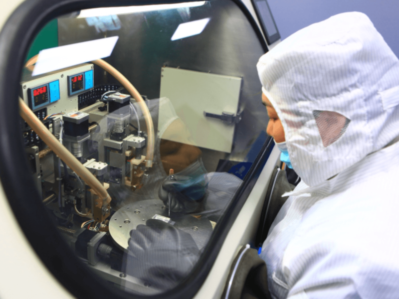
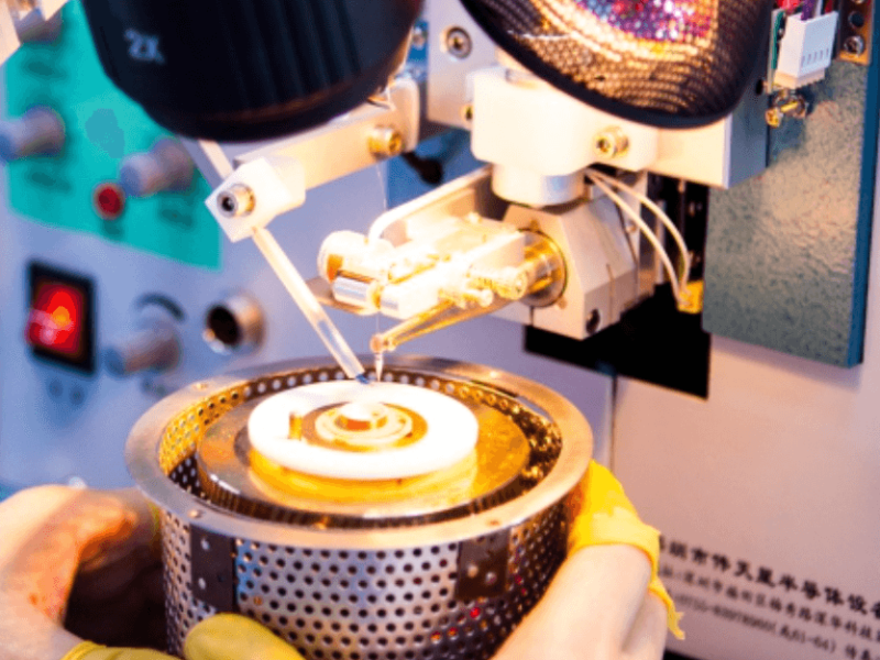
Our Factory - See to Believe





Why Choose Us
Comprehensive Solutions for All Your Navigation Needs
Commercial Grade Coverage
Bias Stability: >0.2°/h
Solution: MEMS based Gyroscope/IMU/INS
Applications: car navigation, unmanned aerial vehicles, transportation, robotics etc.
Tactical Grade Coverage
Bias Stability: 0.05°/h-0.2°/h
Solution: Fiber Optics and MEMS based Gyroscope/IMU/INS
Applications: armored vehicles operations, anti-aircraft artillery, precision targeting etc.
Navigation Grade Coverage
Bias Stability: ≤0.05°/h
Solution: Fiber Optics & Ring Laser Gyroscope/IMU/INS
Applications: medium and long-range guidance, military aviation, satellites



Faqs
Answers to Your Questions
An Inertial Navigation System (INS) uses inertial sensors to measure changes in motion, which helps determine the velocity, orientation, and position of an object.
The IMU, a component of the inertial navigation system, consists of sensors such as accelerometers, gyroscopes, and sometimes magnetometers.
More details:
- Accelerometers gauge an object's acceleration, tracking its changing velocity.
- Gyroscopes detect changes in angular velocity.
- Magnetometers assess the Earth’s magnetic field's strength and direction, determining orientation relative to magnetic north. The system adjusts for the discrepancy between true north and magnetic north. However, magnetic interference sources can affect a magnetometer's accuracy in most vehicles.
These sensors each have limitations, but they work better when combined. By measuring these three sensors, the inertial navigation system calculates traveled distance and heading.
An inertial navigation system measures:
- Pitch
- Roll
- Heading
An INS also incorporates a GNSS receiver, adding another sensor. This provides an absolute position rather than a relative one. While an INS alone can determine position relative to the inertial frame of reference, combining it with GNSS provides an accurate global position.
An inertial navigation system is self-contained and doesn't need satellite signals or base stations to determine position.
GNSS relies on satellite information for positioning. It's widely used in civilian, commercial, and defense applications, though it can be disrupted by atmospheric conditions and multipathing. GNSS signals can also be obstructed by tunnels or intentionally interfered with through jamming and spoofing, especially in military scenarios.
When used together, these two systems provide highly accurate positioning, with the inertial navigation system maintaining accuracy in GNSS-denied environments, enhancing GNSS navigation data.
An INS includes an Inertial Measurement Unit (IMU) and a computational unit. Starting from a known position and orientation (the inertial frame of reference), the IMU tracks changes in velocity and rotation, sending raw data to the INS computational unit, which then accurately determines the new position and orientation.
Inertial navigation systems reliably provide position data. They range from lightweight MEMS (micro-electromechanical systems) to dynamic fiber optic gyroscopes (FOG), and advanced digital fiber optic gyroscopes (DFOG).
INS is especially beneficial in environments where GNSS (global navigation satellite system) is unavailable. GNSS can be disrupted in tunnels or underwater. It can also suffer from multi-pathing or atmospheric interference. While this is a minor issue for phone navigation, precise positioning is critical for aerial surveying or defense applications.
Combining INS with GNSS is more reliable, as INS mitigates errors that GNSS alone might encounter. INS can operate effectively without base station communication, making it suitable where GNSS is inaccurate or unavailable.
Various inertial navigation systems offer different levels of accuracy.
High-end INS using fiber optic gyroscopes (FOG) are accurate within centimeters, suitable for aerospace exploration, AUVs, and defense applications. Unlike GNSS, INS is immune to jamming or spoofing as it doesn't rely on external references like satellites or base stations. GuideNav also offer cost-effective MEMS based INS for applications with less accuracy requirements.
Calibrating an INS ensures that sensor output results are accurate and consistent within specified operating conditions. Calibration involves comparing INS outputs with reference information and adjusting co-efficiency factors to match the two.
INS output can vary due to several factors, such as:
- Temperature – Affects INS output across a range of temperatures.
- Systematic error sources from accelerometers and gyroscopes including:
- Sensor bias
- Sensor output scale factor
- Sensor cross-axis sensitivity
- Sensor axis misalignment
- MEMS gyroscope G sensitivity
- Magnetic Field – INS units with magnetometers for heading determination can be affected by magnetic field changes (e.g., ferrous objects or magnets causing static interference). This error is typically calibrated once the INS is installed in its final position on a vehicle to account for static magnetic interference sources. All GuideNav products have built-in magnetic calibration software to address this issue.
INS calibration involves equipment like temperature chambers, leveling tables, rate tables, and gimbals. All GuideNav products are calibrated, tested, and conform to relevant industry standards before shipping.
INS sensors fall into five performance grades, mainly based on gyroscope performance.
While INS also uses accelerometers and magnetometers, gyroscope cost vs. performance primarily determines the performance grade. MEMS-based INS performance ranges from consumer to tactical grade, but advances in MEMS and data fusion technologies have pushed MEMS-based INS performance towards high-end tactical grade.
Performance grade: Consumer
- Gyro Bias Stability: over 20 °/h
- Cost: $
- Example Applications: Motion detection
- Sensor Technology: MEMS
Performance grade: Industrial/Tactical
- Gyro Bias Stability: 5 – 20 °/h
- Cost: $$
- Example Applications: Robotics
- Sensor Technology: MEMS Based
Performance grade: High-End Tactical
- Gyro Bias Stability: 0.1 – 5 °/h
- Cost: $$$
- Example Applications: autonomous systems
- Sensor Technology: MEMS / FOG (Fiber-optic gyroscope) /RLG (Ring laser gyroscope)
Performance grade: Navigation
- Gyro Bias Stability: 0.01 – 0.1 °/h
- Cost: $$$$
- Example Applications: Aircraft navigation
- Sensor Technology: FOG/RLG
Performance grade: Strategic
- Gyro Bias Stability: 0.0001 – 0.01 °/h
- Cost: $$$$$
- Sensor Technology: FOG/RLG
