Inertial sensors, by nature, are imperfect. Bias drift, random walk, and thermal sensitivity are not anomalies—they’re expected behaviors. What matters is not eliminating these errors, but managing them.
Over the years, I’ve learned that reliable inertial navigation doesn’t come from sensor specs alone—it comes from how well you understand and compensate for those imperfections. Whether you’re using MEMS or FOG, success depends on what happens after the sensor starts reporting data.
Inertial navigation accuracy is ultimately limited by how well sensor errors are modeled and compensated. From bias drift to random walk, effective mitigation requires a combination of hardware design, calibration routines, and real-time algorithmic correction.
Inertial navigation isn’t limited solely by the hardware. Hardware performance sets the floor, but the ceiling is determined by how effectively errors are managed.
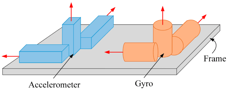
Table of contents
Why Error Compensation Is the Real Bottleneck in INS?
Inertial navigation systems don’t usually fail suddenly—they degrade quietly. What starts as a tiny bias in the gyroscope or a slight offset in the accelerometer slowly becomes a growing error in attitude, velocity, and position. I’ve seen INS drift from sub-meter accuracy to unusable within minutes—not because the sensors were faulty, but because the error wasn’t managed.
No matter how accurate your IMU claims to be on paper, an uncompensated INS will always drift. And in GNSS-denied environments, that drift becomes mission-critical. Effective compensation isn’t a bonus feature—it’s the foundation of a reliable INS.
Categorizing INS Errors: What You Can Model vs. What You Can’t
When working with inertial navigation systems, one of the first things I look at is how the errors behave over time. Some are predictable-others are not. And that difference matters a lot when it comes to compensation.
Systematic errors: predictable and correctable
These are repeatable across time and temperature if left uncorrected:
- Bias drift in gyroscopes and accelerometers
- Scale factor nonlinearity
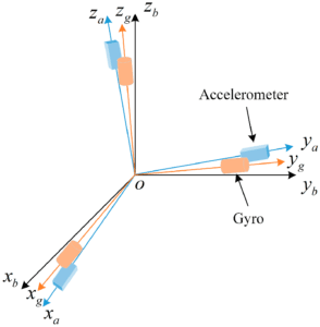
- Slight misalignments between sensor axes
- Thermal sensitivity that shifts output depending on environment
With a solid calibration routine, these errors can usually be measured once and compensated consistently—as long as your conditions stay within bounds.
Random errors: unpredictable, but characterizable
Then there are errors that can’t be removed, only modeled. These include:
- Angular Random Walk (ARW)
- Velocity Random Walk (VRW)
- Sensor white noise
- Vibration-induced artifacts, especially in mobile platforms
Takeaway: Systematic errors are solved in the lab. Random errors are fought in the field.
How INS Errors Propagate Over Time?
Before we talk about compensation, it’s essential to understand how errors actually behave inside an INS. They don’t just appear—they grow, accumulate, and interact with system dynamics in ways that are often underestimated. Let’s break down how that plays out.
Small errors don’t stay small.
In an inertial navigation system, even a slight bias in the gyroscope or a micro-g of acceleration error will grow over time. That’s because INS works by integrating sensor data—meaning any error compounds at every step.
Integration is a multiplier.
A drift in orientation affects velocity. A velocity error then impacts position. This chain reaction is why a system with seemingly good specs on paper can still drift hundreds of meters after 30 minutes of GNSS denial.
Motion profile matters. A lot.
The way your system moves will influence which errors dominate. In static platforms, long-term bias and thermal drift take over. In high-dynamic systems—like drones, missiles, or fast rovers—scale factor nonlinearity and time delay become more critical than bias itself.
Long missions amplify everything.
Whether it’s a 12-hour survey route or a 2-minute missile flight, the longer your INS operates without correction, the more important your error modeling becomes.
Modeling Sensor Errors for Effective Compensation
Before you can correct anything in an INS, you need to understand what you’re correcting. A sensor’s bias, drift, and noise aren’t bugs—they’re behaviors. And unless you model them properly, your compensation strategy is just guesswork.
I typically rely on four key modeling methods. Each targets different types of errors, and together, they give you a clear picture of how your system will behave—not just in the lab, but in the field.
| Modeling Method | Main Purpose | Error Types Addressed | Why It Matters |
|---|---|---|---|
| Allan Variance | Analyze how sensor noise evolves over time | ARW, bias instability, random drift | Essential for filter tuning and sensor grading |
| Six-Position Calibration | Estimate fixed biases and misalignment | Bias, scale factor, axis misalignment | Enables accurate static error removal |
| Thermal Calibration | Map output variation across temperatures | Temp-induced bias and gain drift | Critical for real-world outdoor and mobile platforms |
| PSD Analysis | Understand sensor noise by frequency | White noise, low-frequency wander | Informs filter design without suppressing real motion |
Tip: Combine at least three of these methods before trusting your INS in any GNSS-denied or long-duration mission.
Hardware-Based Error Mitigation Techniques
Good software can’t save bad hardware. In inertial navigation systems, mechanical, thermal, and electrical design choices directly affect long-term stability. These are the core techniques I rely on to build robust INS platforms.
- Vibration isolation is essential.
Unfiltered mechanical vibration creates false motion signals. Using tuned isolators or properly damped sensor mounts can reduce high-frequency noise significantly, especially on tracked vehicles or rotorcraft.
- Thermal consistency keeps your calibration valid.
Sensor output drifts with temperature. Passive insulation or active heating can help maintain the operating temperature within the range you calibrated for.
- Power noise becomes signal noise.
Voltage ripple and EMI cause subtle, persistent corruption of analog and digital signals. I always use clean power rails, low-noise regulators, and strict analog/digital separation.
- Mounting precision affects alignment.
Even tiny mechanical shifts can lead to significant errors in attitude and velocity. Use rigid, machined brackets and carefully control IMU orientation and torque.
- Use sensors that match the mission.
Don’t just pick the “best” sensor—choose one that fits your error budget. For long GNSS outages, bias stability matters most. For fast platforms, low ARW and bandwidth take priority.
Bottom line: The best inertial performance starts long before data collection—it starts with how you bolt the sensor to the frame.
Software-Based Compensation Techniques
Once the hardware is stable, software takes over. This is where most of the drift control happens, and also where a good model can make a modest sensor perform like a great one. Here’s how I approach it in practice:
- Start with proper calibration.
Use static and dynamic procedures to measure bias, scale factor, misalignment, and temperature response. Without a good calibration baseline, everything else is guesswork.
- Use filters that match your dynamics.
Extended Kalman Filters (EKF), Unscented Kalman Filters (UKF), or complementary filters—pick based on your motion profile and available aiding sources. The wrong filter structure is worse than no filter at all.
- Temperature compensation is non-negotiable.
Whether you’re using a FOG or MEMS IMU, sensor behavior shifts with temperature. Real-time correction using internal or external temperature sensors can reduce drift by an order of magnitude.
- Adaptive filtering improves survivability.
In multi-phase missions (e.g., launch, cruise, descent), sensor noise characteristics change. Adaptive filter tuning—based on speed, vibration, or environmental data—lets your system adjust as needed.
- Closed-loop correction keeps things bounded.
Use GNSS, odometry, barometer, or magnetometer updates to bound error growth. Even a low-rate correction every few seconds dramatically improves performance in long-duration tasks.
What matters most: Software can’t invent accuracy—but it can protect it, stretch it, and recover it when things go wrong. And that’s exactly what a good INS needs to do.

The Role of Sensor Fusion in Suppressing INS Drift
Even the best inertial navigation system will drift—it’s not a flaw, it’s physics. The real question is how to bound that drift using other sensors. That’s where sensor fusion becomes the most powerful tool in the system.
GNSS + INS: The classical solution
When GNSS is available, even intermittently, it provides absolute position updates to bound the INS drift.
Best for: long-duration missions, mobile mapping, UAVs
Advantage: accurate corrections, mature filters (EKF)
Caveat: vulnerable to jamming, signal dropout, and multipath
FOG + MEMS Hybrid: Balancing precision and cost
Combining a stable FOG with responsive MEMS gives you the best of both worlds—low drift plus fast reaction.
Best for: mid-size UAVs, naval platforms, robotic systems
Advantage: better ARW + lower SWaP
Caveat: requires careful integration and cross-calibration
Vision / LiDAR + INS: GNSS-free continuity
Visual odometry or LiDAR SLAM can provide relative pose data when GNSS is unavailable, such as indoors or underground.
Best for: autonomous vehicles, tunnels, warehouses, mines
Advantage: fully self-contained
Caveat: line-of-sight needed, sensitive to lighting or feature density
Timing is everything. Fusion only works if your sensors are synchronized. Misaligned timestamps cause more harm than good.
In practice: Fusion isn’t about adding more sensors—it’s about knowing which one to trust at the right time.
GuideNav’s Approach to INS Reliability
After everything I’ve seen in the field—across UAVs, survey vehicles, marine systems—one thing stays true: the real performance of an INS comes from everything around the sensor.
At GuideNav, that’s exactly where we focus.
- Every unit is fully calibrated across temperature and axes, not just batch-tested.
- We provide real Allan variance dataand filter tuning support—not just spec sheets.
- Our FOG and MEMS models come with field-ready integration tools: stable timing, clean interfaces, and support for fusion.
- And because we’re ITAR-free, our systems are ready for global deployment in defense, industrial, or research programs.
You don’t just get a sensor—you get a navigation platform you can trust when other systems drop out.