IMU temperature drift is a stubborn source of gyroscope error: as temperature changes, gyro bias shifts and a static unit appears to be rotating. Because this drift integrates over time, even small bias can grow into significant attitude or heading error in UAVs, AGVs, robots, and stabilized platforms. The effective solution is systematic: reduce IMU temperature drift through hardware design, characterize it across temperature during calibration, and compensate it online in real time.
IMU temperature drift is a major cause of accuracy degradation in inertial systems. Through hardware optimization, full-range thermal calibration, and online compensation, engineers can significantly reduce drift and ensure stable attitude performance.
IMU temperature drift arises from the physical behavior of both MEMS and FOG devices. As temperature changes, the sensor’s bias shifts, and if uncorrected, this drift accumulates into long-term attitude errors. Managing IMU temperature drift requires understanding how temperature affects the sensor, characterizing its drift through calibration, and applying real-time compensation. When supported by proper hardware design, filtering, and sensor fusion, this drift becomes predictable and fully manageable.
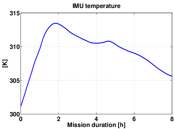
Table of contents
Understanding Gyroscope Temperature Drift
Before exploring how to mitigate IMU temperature drift, it is important to understand what this phenomenon represents. Temperature drift is not random noise—it is a systematic change in bias as the sensor’s internal temperature varies. Because this bias is integrated into attitude estimation, IMU temperature drift can accumulate into large heading or orientation errors during extended operation.
A gyroscope’s output is:
Measured angular rate = true rate + bias + noise
IMU temperature drift refers to the bias term changing as temperature changes, and this mechanism differs for MEMS and FOG gyroscopes.
MEMS Gyroscopes
MEMS-based IMU temperature drift originates from elastic modulus changes, resonant frequency shifts, damping variations, ASIC gain drift, and packaging stress. These effects often cause significant warm-up drift or bias shifts during fast temperature transitions.
FOG Gyroscopes
FOG devices exhibit lower IMU temperature drift but are still influenced by optical phase variations, wavelength shifts in the light source, fiber coil expansion, and thermal stress. Their drift is smoother yet must still be modeled and compensated.
Why Drift Becomes a Serious Attitude Error
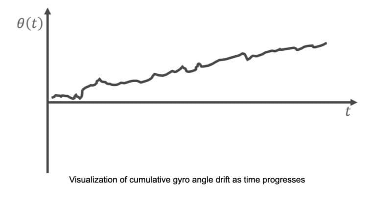
Even though temperature drift may appear small at the moment it occurs, its impact becomes severe once it enters the attitude estimation process. Gyroscopes measure angular rate, and attitude is obtained by integrating this rate over time. Any uncorrected bias—no matter how small—continues to accumulate, producing growing errors in roll, pitch, and especially heading during long-duration operation.
Gyro bias is integrated over time:
Attitude error ≈ ∫ bias × time
This is why a seemingly minor bias such as 0.01 °/s can produce several degrees of orientation error within minutes. The longer the mission and the fewer external references available, the more temperature drift dominates overall navigation accuracy.
Three Core Engineering Methods to Mitigate Temperature Drift
Mitigating gyroscope temperature drift requires a layered engineering approach that addresses the issue at its origin, models it under controlled conditions, and corrects it continuously during operation. Engineers typically apply three complementary methods: hardware optimization, offline thermal calibration, and online real-time compensation.
(1) Hardware Optimization: Reducing Drift at the Source
Hardware-level improvements greatly influence inherent gyro stability. Effective strategies include selecting low–temperature-coefficient sensors, using thermally stable structural materials, maintaining symmetric layouts, and managing internal heat flow. High-grade IMUs may also integrate a heater or thermal-control module to keep the sensor at a stable operating temperature, minimizing intrinsic drift.
(2) Offline Temperature Calibration: Building a Bias–Temperature Model
During manufacturing, the IMU is placed in a temperature chamber and swept across its entire operating range (e.g., −40°C to +85°C). Bias values are recorded at each temperature point, then fitted into a compensation model—linear, polynomial, or piecewise. The model coefficients are stored in firmware and form the basis for accurate real-time correction.
(3) Online Compensation: Correcting Drift in Real Time
With a bias–temperature model established, the IMU compensates drift during operation. A temperature sensor near the gyro core provides real-time temperature readings, the firmware computes the expected bias using the model, and this bias is subtracted from the raw measurements. This counteracts drift caused by warm-up behavior, internal heating, and ambient temperature changes.

Beyond Compensation: Filters and Sensor Fusion for Long-Term Stability
Even with strong hardware design, precise calibration, and real-time compensation, small residual drift will always remain. Over long operating periods, these residual errors can accumulate, so high-performance systems add filtering and sensor fusion for stability.
Filtering Techniques
Low-pass or adaptive filters stabilize the bias estimate and dampen noisy temperature transitions. Static detection methods allow the system to update bias estimates whenever the IMU is stationary, further improving long-term stability.
Sensor Fusion
Fusion algorithms introduce external references to suppress accumulated drift. Typical aiding sources include accelerometers for gravity-based pitch/roll correction, magnetometers or GNSS for heading stabilization, and odometry, vision, or LiDAR for long-duration navigation. EKF/UKF-based fusion anchors the system to absolute references, preventing temperature-driven drift from dominating performance.
Choosing the Right IMU: MEMS vs. FOG
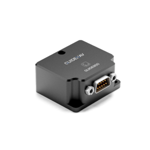
Selecting the correct IMU early is one of the most effective ways to avoid temperature-drift limitations later. MEMS IMUs are ideal when small size, low power, and cost efficiency are priorities, and when external aiding is available. They work well for short to medium mission durations and moderate environmental conditions.
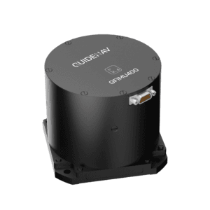
FOG IMUs are the better choice when long-term stability, high heading accuracy, or wide temperature variations are expected. They are preferable for missions that cannot rely on GNSS or other external corrections.
Simple guideline:
- If your system can rely on fusion and needs low SWaP → choose MEMS.
- If your system cannot tolerate accumulated drift → choose FOG.
Building a Stable System with the Right GuideNav IMU
IMU temperature drift becomes manageable when addressed through proper engineering: hardware optimization, temperature calibration, real-time compensation, filtering, and sensor fusion. With these measures in place, UAVs, AGVs, robots, and defense systems can maintain stable performance even under demanding thermal conditions.
GuideNav provides IMUs built with strong thermal stability, carefully designed calibration workflows, and reliable compensation algorithms. Selecting a GuideNav IMU that matches your operational environment and accuracy needs ensures your system begins with a solid thermal foundation—minimizing IMU temperature drift and improving long-term reliability.