In theory, an Inertial Measurement Unit (IMU) can perform odometry — measuring how far a vehicle has traveled by integrating its acceleration and angular rate over time. However, in reality, this “inertial-only odometry” is impractical. The problem lies in error accumulation: even tiny sensor biases cause position drift that grows exponentially with time. Within seconds, the calculated trajectory diverges far from reality.
For autonomous driving and robotics, where localization accuracy must remain within centimeters, an IMU alone simply cannot provide reliable odometry.
An IMU can theoretically compute odometry through double integration, but bias and noise make it drift exponentially over time. Real-world navigation systems therefore rely on IMU fusion with GNSS, LiDAR, or cameras to maintain precision and stability.
Inertial navigation sounds simple — measure motion and calculate distance. But in practice, even small sensor errors grow fast and ruin accuracy. An IMU is a crucial part of every navigation system, but it can’t work alone. This article explains why pure IMU odometry fails and how sensor fusion transforms it into a reliable tool for precise positioning.
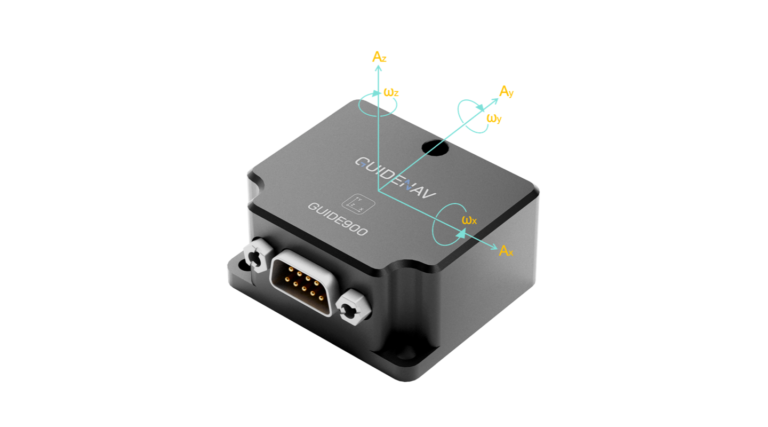
Table of contents
Why the IMU Can Theoretically Perform Odometry
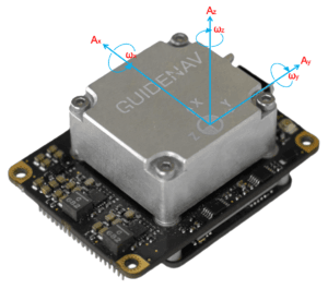
An Inertial Measurement Unit (IMU) measures three-axis acceleration and three-axis angular velocity.
Through continuous integration of these signals, the system can theoretically compute:
- Orientation (Attitude):by integrating angular velocity.
- Velocity:by integrating linear acceleration.
- Position:by integrating velocity once more.
This is the fundamental principle of the Inertial Navigation System (INS) -a self-contained navigation method that relies solely on motion sensors. In an ideal case with perfectly calibrated sensors and no noise, an IMU could continuously determine a vehicle’s movement and estimate its trajectory relative to its starting point. That’s why, in theory, an IMU can perform odometry without any external reference.
Why It Fails in Practice: The Error Accumulation Problem
Although the theory makes sense, every IMU suffers from inherent sensor errors. These small biases and noises are magnified dramatically during the process of double integration, which converts acceleration into position. Over time, even tiny imperfections cause large and rapidly growing drift.
Position Error Grows Quadratically with Time
If the accelerometer contains a small constant bias ba (m/s²), the accumulated velocity and position errors increase over time as:
This means position error grows proportionally to the square of time. Even a tiny offset can lead to dramatic drift.
For example, assume the accelerometer bias ba 0.01 m/s2 — a very typical value for commercial-grade MEMS IMUs.
| Time | Position Error |
|---|---|
| 1 s | 0.005 m |
| 10 s | 0.5 m |
| 30 s | 4.5 m |
| 60 s | 18 m |
After only one minute (60 s) of operation, the estimated position error can reach about 18 meters, which is far beyond the localization accuracy required for autonomous driving (usually < 0.1–0.3 m).
Gyroscope Bias Causes Attitude Drift
A small gyroscope bias might seem insignificant, but over time it leads to noticeable attitude estimation errors. Once the orientation drifts, the IMU can no longer correctly separate gravity from true motion — it fails to “remove gravity” from the accelerometer data. When this happens, part of the gravity vector is mistakenly treated as horizontal acceleration, making the system believe the vehicle is moving even when it is stationary. This false acceleration keeps integrating into fake velocity and ultimately results in explosive position drift.
Other Error Sources
Beyond bias, real-world IMUs are affected by multiple error sources that amplify over time:
| Error Source | Impact |
|---|---|
| Scale-factor error | Incorrect scaling of acceleration or angular rate measurements. |
| Misalignment | Non-orthogonal sensor axes introduce projection errors. |
| Temperature drift | Bias shifts with temperature, degrading calibration. |
| Vibration noise | Mechanical noise integrates into position drift. |
| Initial alignment error | Small startup attitude errors cause long-term deviation. |
Even small imperfections, when combined, cause the navigation output to diverge rapidly. In practice, pure inertial odometry becomes unusable within seconds, even for high-grade sensors.
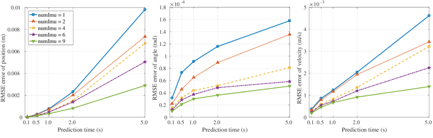
Precision Evaluation: How Long Can IMU-Only Odometry Last
Even with advanced sensors, inertial-only odometry can stay accurate for only a short period before drifting out of control. Since position error increases quadratically with time, the duration of reliable operation mainly depends on the IMU’s grade and its bias stability.
| IMU Grade | Typical Bias | Position Error (10 s) | Position Error (60 s) | Practical Use |
|---|---|---|---|---|
| Consumer Grade | > 0.01 m/s² | > 0.5 m | > 18 m | Completely unusable |
| Industrial Grade | ~ 0.001 m/s² | ~ 5 cm | ~ 1.8 m | Usable for short tests only |
| Navigation Grade | < 0.0001 m/s² | ~ 0.5 cm | ~ 18 cm | Accurate for a few seconds; still needs fusion |
| Tactical Grade | Extremely low | Controllable | Few meters | Usable for military / aerospace; high cost |
Even the highest-grade IMUs cannot avoid drift forever. That’s why modern autonomous systems always rely on sensor fusion — combining IMU data with GNSS, LiDAR, or visual inputs — to maintain long-term accuracy and stability.
The IMU’s Role in Modern Navigation -Sensor Fusion at the Core
Although an IMU cannot independently perform odometry, it plays an irreplaceable role in modern navigation. Instead of being the main positioning source, it acts as the high-frequency backbone that enhances and stabilizes other sensors.
High-Frequency Motion Estimation
IMUs operate at hundreds to thousands of hertz, much faster than GNSS, LiDAR, or cameras.
This high update rate lets them capture rapid motion and fill the gaps between slower sensors — providing smooth, continuous motion awareness for the entire navigation system.
Short-Term Prediction and Smoothing
When GNSS signals are lost — inside tunnels, under bridges, or in dense urban areas — the IMU provides short-term dead reckoning to maintain a continuous trajectory.
It predicts the system’s state (position, velocity, orientation) for a few seconds, ensuring smooth transitions until external measurements become available again.
This bridging capability makes the IMU essential for robust navigation in GNSS-denied environments.
The Core of Sensor Fusion
In modern localization, the IMU acts as the dynamic core of multi-sensor fusion systems. Its high-rate inertial data provides continuous motion information, while low-rate but drift-free measurements from other sensors — such as GNSS, LiDAR, or cameras — constantly correct accumulated errors, keeping navigation both stable and precise.
| Fusion Method | Sensor Combination | Application |
|---|---|---|
| GNSS/IMU Loose or Tight Coupling | RTK-GNSS + IMU | High-precision land or aerial navigation |
| Visual-Inertial Odometry (VIO) | Camera + IMU | SLAM, UAVs, robotics |
| LiDAR-Inertial Odometry (LIO) | LiDAR + IMU | Autonomous driving, mapping |
| Factor Graph or Kalman Filter Fusion | Multiple sensors + IMU | Integrated state estimation |
Conclusion
An IMU alone can estimate motion in theory, but in practice its errors grow too fast to be useful. Even tiny biases quickly cause position drift of several meters within seconds.
Still, the IMU remains essential — it provides high-frequency motion data that other sensors can’t. When fused with GNSS, LiDAR, or cameras, it becomes the core of a stable, precise navigation system.