Most fiber optic IMUs are born for precision — not punishment. Under laboratory conditions, they achieve incredible angular stability. But the battlefield, the launch pad, and the drilling site don’t play by lab rules.
A single 50 g shock pulse can distort a delicate optical coil, producing false rate outputs that spiral into positional drift.
To survive this chaos, engineers have evolved a new generation of ruggedized fiber optic IMUs — integrating mechanical damping, stress-relieved optics, and intelligent bias recovery — ensuring the sensor remains rock-solid even at 90 g shock or 2000 Hz vibration.
Rugged fiber optic IMUs achieve extreme reliability by combining titanium housings, floating coil suspensions, elastomeric and wire-rope isolators, and AI-based signal compensation. These technologies let them function flawlessly under intense vibration and shock where conventional gyros fail.
Precision without durability is a paradox.
A high-grade fiber IMU that fails during launch or firing is no better than a toy gyro. In defense and aerospace systems, survivability defines value. When recoil forces, engine vibration, and continuous shock waves are constant companions, only mechanically and algorithmically hardened IMUs can hold their calibration and maintain truth in motion.
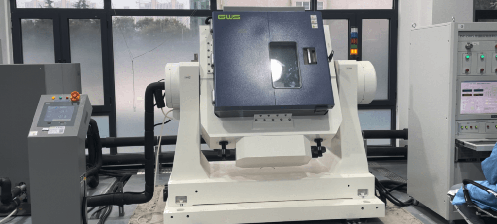
Table of contents
What Makes a Fiber Optic IMU Sensitive to Vibration?
At its heart, a fiber optic gyroscope (FOG) measures rotation through the Sagnac effect — two light beams traveling in opposite directions inside a long, coiled optical fiber. Even nanometer-scale deformation of this coil, caused by twisting, compression, or vibration, can slightly alter the optical path length and generate a false rotation signal.
To preserve accuracy, the fiber coil must be mechanically isolated from external stress while maintaining perfect optical symmetry. Engineers achieve this balance by using low-expansion spool materials, controlled winding tension, and damping interfaces that absorb vibration without disturbing alignment — a precise equilibrium between rigidity and flexibility that defines the reliability of every FOG-based IMU.
How Does Mechanical Shock Affect the Fiber Coil?
A mechanical shock pulse travels through the IMU housing and momentarily compresses and rebounds the fiber coil, distorting its optical path geometry. Even a brief deformation can disturb the precise interference conditions required for accurate rotation sensing.
This temporary distortion changes the effective length of the Sagnac loop, producing a false angular rate spike and creating a short-lived phase imbalance within the optical circuit. The effect appears as a sudden bias jump or transient drift in the output data.
If the system cannot recover bias rapidly, residual strain lingers for several seconds, gradually corrupting attitude accuracy. Under extreme impacts exceeding 60 g, micro-slip between the coil and its spool may even cause permanent scale-factor deviation, requiring recalibration.
What Role Do Structural Materials Play?
Material engineering defines how long precision can survive under stress.
Rugged fiber IMUs rely on optimized structural composition to withstand repeated shocks and vibration cycles.
Key Design Elements:
- Housing:Aerospace-grade 7075-T6 aluminum or titanium alloy, providing exceptional stiffness-to-weight ratio.
- Internal frame:Embedded damping polymers or silicone gaskets absorb micro-strain and decouple the optical coil from chassis deformation.
- Fastening system:Pre-torqued, anti-vibration screws eliminate micro-slip under high-g shock pulses.
Together, these components form a skeleton that transfers heat but not stress — the hallmark of a truly ruggedized fiber optic IMU.
How Do Suspension and Damping Systems Work Inside a Rugged IMU?
Inside a ruggedized fiber IMU, the optical coil is not rigidly fixed — it’s mounted on a carefully tuned floating suspension system designed to absorb and dissipate mechanical energy before it reaches the optics.
Typical configuration includes:
- Elastomeric mounts– isolate low-frequency vibrations (5–200 Hz) such as engine rumble or platform sway.
- Wire rope isolators– attenuate high-frequency content (>500 Hz) from shock or recoil events.
- Dual-stage frames– separate the coil and PCB assemblies to prevent cross-coupled resonance.
This hybrid damping structure can absorb over 90% of transmitted energy, allowing the IMU to remain stable and maintain bias integrity even under 80–90 g shock loads.
How Do Engineers Deal with Long-Term Concerns?
Even with aging tests in place, engineers still face practical challenges when deploying Fiber Optic IMUs and INSs over many years of service. One of the most pressing concerns is bias drift—the tendency for small errors to build up over time. To counter this, systems are often powered on regularly, allowing self-calibration routines to refresh stability and prevent silent degradation.
Another factor is storage conditions. A navigation unit kept in a hot, humid warehouse will age much faster than one stored in a controlled, dry environment. This means shelf life is not only a matter of design but also of logistics and maintenance discipline.
Finally, unlike consumable items that carry a simple “manufacture date + expiration date,” the usable life of a Fiber Optic IMU or INS cannot be stamped with a single number. Instead, it depends on drift models, stress test data, and continuous monitoring of performance thresholds. This makes aging experiments not just a technical necessity, but a roadmap for engineers to manage reliability throughout the system’s lifecycle.
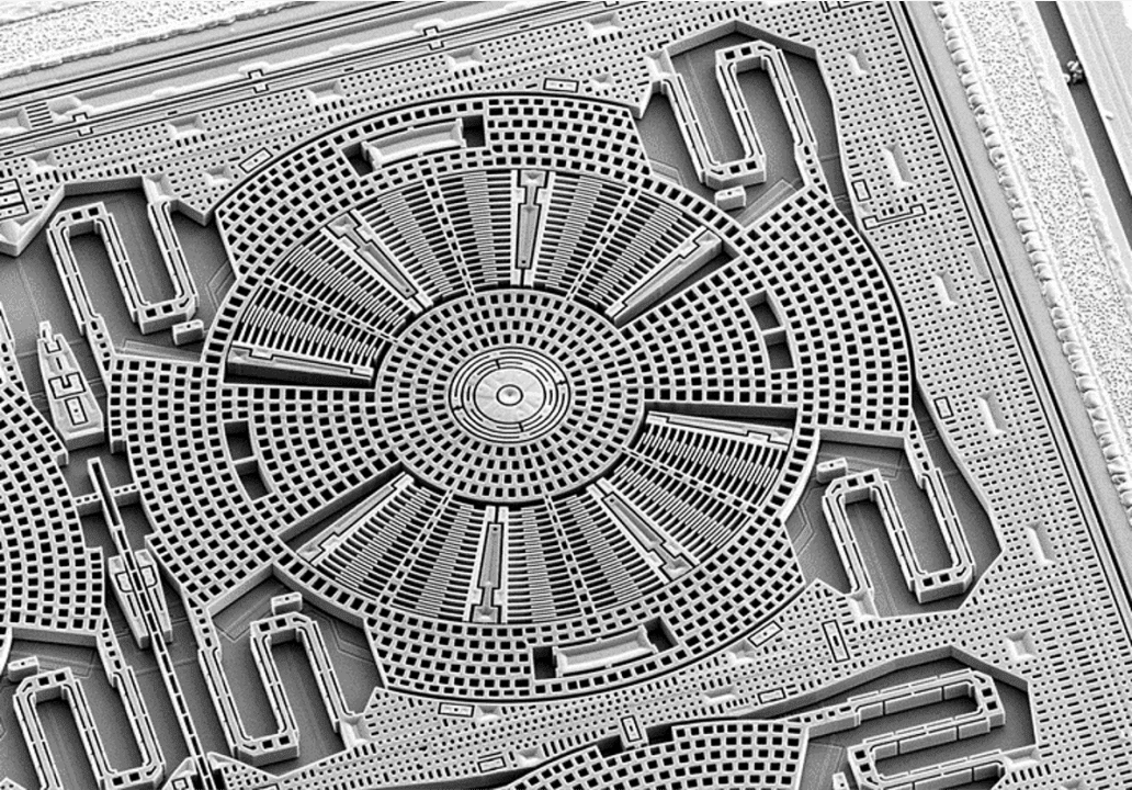
How Is the Fiber Coil Wound to Withstand Vibration?
In a fiber optic IMU, the coil is both the heart and the Achilles’ heel.
Every vibration, every micro-bend, every thermal pulse tries to stretch or twist the optical path — and that distortion becomes drift.
To fight back, engineers build the coil like a precision spring under perfect balance.
The quadrupole winding pattern mirrors each fiber layer against the next, cancelling torsional stress before it reaches the sensing loop.
During manufacturing, the fiber is tensioned and epoxy-bonded under controlled temperature, allowing internal stress to relax instead of accumulate.
Polarization-maintaining fibers and athermal coil formers further stabilize light propagation when heat and vibration strike at once.
The result: an optical coil that doesn’t flinch when the chassis shakes —keeping the Sagnac phase steady, and the IMU bias where it belongs.
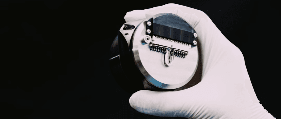
How Are PCBs and Connectors Reinforced Against Shock?
The PCB is the hidden shock absorber of a fiber optic IMU.
Every pulse that reaches the electronics can distort alignment or break solder joints, so the board must be designed to yield without failing.
High-strength polyimide laminates provide controlled flexibility, allowing the surface to deflect microscopically instead of cracking.
Critical ICs and MEMS sensors are anchored with underfill epoxy, spreading impact energy evenly across the board.
Interconnects use flex-ribbon cables that tolerate displacement, while vibration-damped standoffs isolate the PCB from the chassis.
Through this layered mechanical design, the electronic section behaves like a tuned suspension system — quietly absorbing shocks and preserving signal integrity under continuous stress.
How Does Firmware Compensate for Mechanical Shock?
Mechanical resilience alone isn’t enough — the firmware must also know how to think under impact.
Modern fiber optic IMUs integrate shock detection and adaptive compensation algorithms that monitor raw gyro output in real time.
When a sudden pulse or vibration burst occurs, the processor instantly recognizes the transient pattern, freezes bias updates, and isolates corrupted samples before they propagate through the navigation loop.
Once the disturbance subsides, an adaptive Kalman filter recalibrates the zero drift using predictive bias modeling, allowing the IMU to recover within milliseconds instead of minutes.
This closed-loop intelligence turns rugged hardware into a responsive system — one that not only survives mechanical stress, but actively preserves accuracy in the middle of it.
How Is the Fiber Coil Wound to Withstand Vibration?
In a fiber optic IMU, the coil is both the heart and the Achilles’ heel.
Every vibration, every micro-bend, every thermal pulse tries to stretch or twist the optical path — and that distortion becomes drift.
To fight back, engineers build the coil like a precision spring under perfect balance.
The quadrupole winding pattern mirrors each fiber layer against the next, cancelling torsional stress before it reaches the sensing loop.
During manufacturing, the fiber is tensioned and epoxy-bonded under controlled temperature, allowing internal stress to relax instead of accumulate.
Polarization-maintaining fibers and athermal coil formers further stabilize light propagation when heat and vibration strike at once.
The result: an optical coil that doesn’t flinch when the chassis shakes —keeping the Sagnac phase steady, and the IMU bias where it belongs.
Validation and Testing Standards
Ruggedization is proven, not claimed.
Every high-shock fiber IMU must pass military and aerospace environmental testing to verify bias stability and alignment after mechanical stress.
Key standards include:
- MIL-STD-810H (514.8 & 516.8):Vibration and shock profiles up to 40 g, 10–2000 Hz.
- GJB 150A-2009:Multi-axis vibration and high-impact endurance for defense instruments.
- RTCA DO-160G Section 7:Avionics qualification under continuous vibration and temperature change.
Units must maintain full function and nominal bias stability after these tests to earn rugged-grade certification.
What Sets a Rugged Fiber IMU Apart from a Standard One?
A rugged fiber IMU is not merely a reinforced version of a standard model — it embodies an entirely different design philosophy. Every element, from the optical coil to the smallest screw, is engineered to absorb impact rather than resist it, transforming structural durability into true operational reliability.
| Feature | Standard Fiber IMU | Ruggedized Fiber IMU |
|---|---|---|
| Shock tolerance | ≤ 20 g | ≥ 90 g |
| Housing material | 6061 Aluminum | Titanium / 7075-T6 Alloy |
| Coil mounting | Fixed base | Floating suspension |
| Isolation | None | Wire rope + Elastomer |
| PCB structure | Conventional FR-4 | Reinforced polyimide, underfilled components |
| Connector design | Rigid plugs | Flex-ribbon / spring-mounted |
| Bias recovery | Static algorithm | Adaptive filter |
| Application | UAVs, labs | Missiles, tanks, drilling rigs |
These differences go far beyond durability — they redefine reliability itself.
A rugged fiber IMU maintains truth in motion under violence, heat, and fatigue, turning precision from a lab specification into a battlefield guarantee.
GuideNav — Redefining Rugged Fiber IMUs
A rugged IMU is measured by survival, not by specifications. Guided by this principle, GuideNav engineers fiber optic IMUs that deliver unwavering precision under the world’s harshest conditions. Each unit combines titanium housings, floating optical coils, and adaptive bias correction algorithms to maintain stability through continuous vibration and up to 90 g of shock. These systems don’t merely resist mechanical stress — they master it, turning structural endurance into operational reliability. In environments where every degree and every second matter, GuideNav defines what military-grade performance truly means.