On paper, many MEMS accelerometers look identical—until they don’t. Slight differences in bias drift, bandwidth, or shock tolerance can ripple through flight controllers, guidance systems, and industrial robots, degrading performance in ways specs alone won’t reveal. What follows is distilled from years of lab validation, field integration, and system-level testing.
Selecting a MEMS accelerometer isn’t just about datasheet numbers. Real-world factors like thermal drift, vibration endurance, and in-field bias stability often determine system performance where it counts. This guide focuses on what truly matters across defense, aerospace, and robotic platforms.
System-level reliability begins with sensor-level decisions. Let’s take a closer look.
Table of contents
What Is a MEMS Accelerometer and How Does It Work?
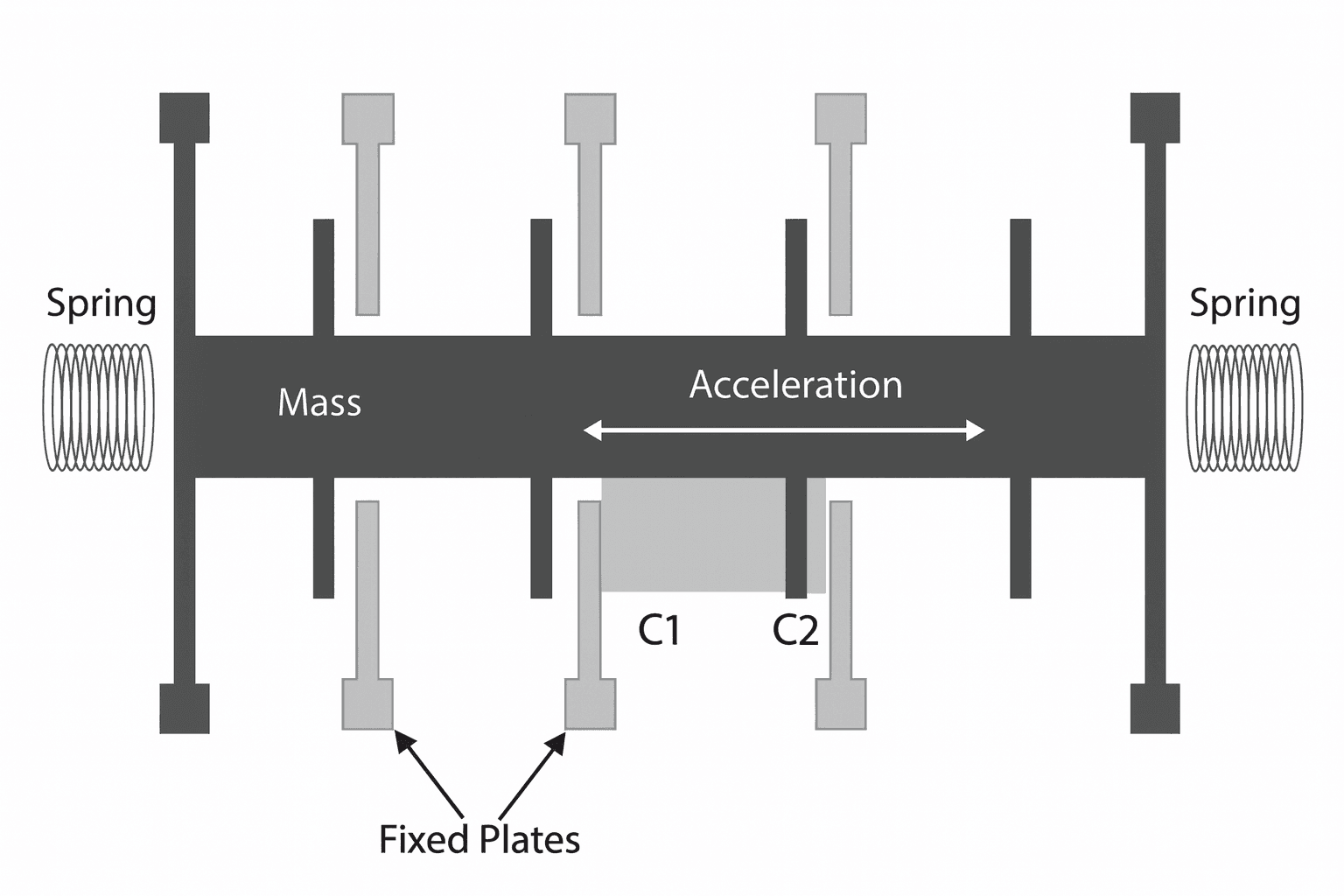
A MEMS accelerometer is a microelectromechanical sensor designed to measure linear acceleration along one or more axes. It detects motion by tracking changes in capacitance as a tiny proof mass moves within its internal structure.
When acceleration occurs, the mass shifts slightly, altering the sensor’s electrical output. This allows it to capture both static forces (like gravity) and dynamic forces (such as vibration, shock, or movement).
Compared to traditional mechanical or piezoelectric types, MEMS-based accelerometers are smaller, lighter, and more power-efficient. They’re widely used in inertial navigation systems (INS), flight controllers, robotic platforms, and defense-grade weapon systems, where compact, rugged, and responsive motion sensing is essential.
Which Specs Define a High-Quality MEMS Accelerometer?
When comparing MEMS accelerometers, looking beyond just the g-range is critical. Four core specifications directly influence performance:
- Bias stabilitydetermines how much drift accumulates over time. For navigation systems, values below 50 µg are preferred.
- Noise densityaffects signal clarity. Lower values (e.g., <100 µg/√Hz) allow for more accurate motion detection.
- Bandwidthdefines responsiveness. Applications involving fast motion—like UAV flight control—often need over 1 kHz.
- Measurement rangevaries by use case. High-g accelerometers (up to 20,000g) are used for impact monitoring, while low-g types (±2g to ±10g) suit tilt or slow movement.
Choosing the wrong spec—too noisy, too narrow, or too imprecise—can cascade into control instability, degraded accuracy, or mission failure.
Can MEMS Accelerometers Handle Harsh Conditions?
Not all MEMS accelerometers are ready for the real world. On paper, many claim wide temperature ranges or high shock limits—but field conditions expose the real gap.
Take vibration as an example. We once tested a sensor on a tracked UGV operating on rough terrain. Within two days, its output bias had drifted by over 500 µg, enough to break alignment in a dead-reckoning system. It had passed all lab tests—but not the mission.
The same applies to thermal cycling. A sensor in an airborne system may see cabin temperatures swing from –20°C at takeoff to +60°C after hours of engine heat soak. Unless its thermal compensation is truly stable, the error builds silently.
That’s the cost of trusting numbers over proven durability.
True ruggedness means surviving not just the extremes—but the repetition. Always look for sensors validated under mission-profile loads, not just spec-sheet conditions. In aerospace and defense, resilience under stress isn’t optional—it’s operational.
What Should You Know About Power, Interface, and Data Rate?
When integrating a MEMS accelerometer into embedded systems, electrical compatibility is just as important as performance specs.
Power consumption impacts overall system efficiency—especially in UAVs, handheld devices, and autonomous robots. Many tactical-grade sensors operate under 1 mA, but high-speed modes or self-tests may raise current draw significantly.
Interface type defines integration workload. SPI is fast and robust, suitable for navigation and control loops. I²C is simpler but slower, often used in monitoring or non-critical timing applications. Some sensors also offer analog output for legacy systems.
Output data rate (ODR) must match your system’s processing speed. Flight control or navigation platforms typically need ≥1 kHz, while structural monitoring may only require 100–200 Hz.
Neglecting these parameters can lead to timing issues, unnecessary power drain, or complete communication failure. Always verify electrical specs against your system design early in the selection process.

What Makes GuideNav a Reliable Vendor for MEMS Accelerometers?
As a true sensor-level manufacturer—not just an integrator—GuideNav designs and builds MEMS accelerometers from the ground up. This gives us full control over performance, customization, and long-term support. In real deployments, it’s this depth—not just datasheet specs—that determines whether integration succeeds or stalls.
That’s why engineers trust GuideNav—not just for sensor performance, but for the complete support ecosystem behind it.
Application-aligned support
Our engineers collaborate from concept to deployment, offering real-time assistance during sensor tuning, platform testing, and integration troubleshooting.
Flexible customization
Need a specific bandwidth, output range, or connect? We adapt our MEMS accelerometers to meet your platform’s exact electrical and mechanical needs.
Long-term supply stability
GuideNav maintains full production traceability and lifecycle planning, ensuring stable delivery across years of industrial or defense programs.
ITAR-free and export-friendly
Our MEMS sensors are compliant for global use and free from U.S. re-export restrictions—making them ideal for international programs.
Deplyment-ready documentation
From complete datasheets to 3D models and firmware guides, our technical documentation reduces integration time and risk.
Choosing a sensor is just the beginning. Choosing GuideNav means choosing a partner for the entire development cycle.