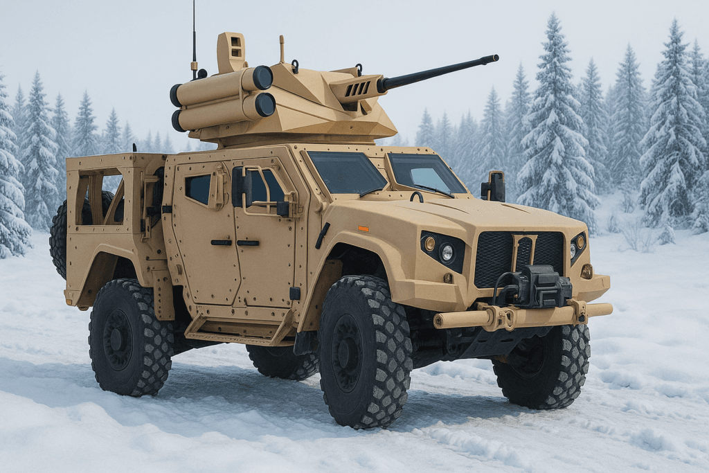
In vehicle-mounted LRF systems, inadequate inertial stabilization often results in misalignment, unstable ranging, and degraded system performance under dynamic conditions.
Based on real-world experience, FOG gyros outperform MEMS in terms of long-term stability, vibration immunity, and thermal robustness in vehicle-mounted LRF applications. MEMS is still viable for space-constrained or budget-sensitive platforms, but requires careful compensation design.
If you’re engineering for performance under motion, this trade-off deserves a closer look.
Table of contents

What Does an Inertial Sensor Do in LRF Stabilization?
In stabilized laser rangefinder systems, inertial sensors provide the angular rate data necessary to maintain line-of-sight consistency as the platform moves. In my projects, these sensors are typically integrated with a gimbal control loop, enabling fast real-time corrections to counteract vehicle pitch, yaw, and vibration.
Without accurate and responsive inertial feedback, even a high-end LRF will drift off-target during turns, terrain changes, or recoil events—resulting in lost time, degraded accuracy, or tracking failure in mission-critical scenarios.
How Do MEMS and FOG Sensors Work?
In vehicle-mounted LRF stabilization, the sensing principle of the gyroscope directly affects system stability, accuracy, and long-term reliability. The table below summarizes the core differences between MEMS and FOG technologies from an engineering perspective:
| MEMS Gyroscope | FOG Gyroscope | |
|---|---|---|
| Sensing Principle | Vibrating silicon structure detects Coriolis effect | Sagnac effect: optical phase shift in coiled fiber |
| Mechanical Robustness | Sensitive to shock and prolonged vibration | No moving parts; excellent vibration immunity |
| Drift Performance | Higher bias drift; typically 1–3°/hr | Ultra-low bias instability; often <0.1°/hr |
| Thermal Behavior | Susceptible to temperature-induced bias changes | Stable across wide thermal ranges |
| Size & Power | Compact form factor; <1 W typical | Larger housing; 2–5 W power typical |
| Recommended Use Case | Cost-sensitive, space-limited platforms with mild dynamic requirements | High-performance stabilization under sustained motion and vibration |
What Are the Key Performance Metrics for LRF Stabilization?
In my experience designing inertial modules for mobile electro-optical systems, the key performance metrics that determine whether a sensor is suitable for LRF stabilization are always the same: bias stability, angular random walk, bandwidth, shock tolerance, and thermal resilience.
But how MEMS and FOG perform against these benchmarks is very different.
MEMS Performance Summary
MEMS gyros are compact and cost-effective, but under dynamic conditions, their performance tends to degrade due to noise, drift, and thermal sensitivity.
| Metric | Typical MEMS Range | Impact |
|---|---|---|
| Bias Instability | 3–10°/hr | Cumulative pointing error over time |
| Angular Random Walk | 0.1–0.5°/√hr | Noisy tracking in short time scales |
| Bandwidth | 200–400 Hz | May struggle under shock-driven dynamics |
| Shock Tolerance | 2000–8000 g | Sensor structure survives impact, but signal bias may shift or saturate |
| Temperature Range | -40°C to +85°C | Drift-prone under rapid changes |
For compact platforms or cost-sensitive integration where moderate stability is acceptable, MEMS may be sufficient—with careful signal conditioning and regular resets.
FOG Performance Summary
FOG gyros are designed for stability in harsh environments. Their optical architecture offers superior noise rejection and long-term reliability.
| Metric | Typical FOG Range | Impact |
|---|---|---|
| Bias Instability | 0.01–0.1°/hr | Stable long-term tracking |
| Angular Random Walk | < 0.01°/√hr | Smooth, low-noise stabilization |
| Bandwidth | 200–1000 Hz | Fast response under dynamic loads |
| Shock Tolerance | 1000–5000 g (short-duration) | Maintains consistent signal integrity under mechanical shock and vibration |
| Temperature Range | -40°C to +85°C | Minimal drift even in extreme climates |
MEMS may tolerate higher peak shock loads structurally, but often experience signal degradation. FOG may be rated for lower peak shock, but consistently maintain output integrity under dynamic mechanical stress.

Performance Under Vibration and Shock: A Field-Test Perspective
In mobile platforms, vibration and impact are constant, not exceptions. During turret rotation, off-road driving, or recoil events, inertial sensors are subjected to abrupt accelerations that can exceed 3000–5000g.
Observations from Field Projects
- In multiple tracked vehicle tests, MEMS gyros showed observable bias drift after repeated recoil events, especially at elevated temperatures.
- MEMS-based systems also exhibited occasional signal discontinuity during prolonged vibration exposure, requiring periodic re-zeroing.
- In contrast, FOG gyroscopes maintained output integrity, even after sustained shock loading and high-frequency vibration.
Engineering Interpretation
| Criteria | MEMS IMU | FOG Gyroscope |
|---|---|---|
| Response to Shock | May shift bias; requires compensation | High immunity; stable output |
| Behavior Under Vibration | Possible scale factor variation | Minimal impact |
| Long-Term Mechanical Stability | Sensitive to fatigue over time | No wear; optical system is inherently robust |
Recommendation
If the platform is expected to encounter continuous vibration, strong shock, or structural resonance, FOG-based stabilization is significantly more reliable. MEMS sensors may still be used in non-critical subsystems, but should be paired with diagnostic algorithms to detect performance degradation.
Which Technology Offers Better Drift Performance Over Time?
Imagine this:
Two identical LRF stabilization systems are mounted on a mobile platform. One uses a MEMS gyro; the other uses a tactical-grade FOG. Both are switched on at the same time. No GNSS correction. No reset.
- After 10 minutes, both systems track accurately.
- After 30 minutes, the MEMS-based unit shows subtle drift—just enough to require software correction.
- After 60 minutes, the MEMS sensor has accumulated several degrees of misalignment. The system struggles to maintain stable line-of-sight.
- The FOG system, meanwhile, continues to operate with near-zero drift, maintaining sub-degree pointing accuracy without correction.
This isn’t theoretical—it’s what I’ve repeatedly observed in live platform trials.
If your system needs to run continuously and precisely over long durations, FOG is the sensor that holds its ground.
Thermal Stability: What Happens When the Temperature Shifts?
Environmental temperature isn’t static—especially in mobile platforms. I’ve tested systems that started at 25°C and climbed to over 60°C in direct sunlight. Here’s what typically happens:
MEMS-based systems
Even a ±10°C change can shift the sensor bias enough to cause noticeable line-of-sight deviation. Some sensors include temperature compensation curves, but under rapid or uneven heating, corrections often lag or fall short.
FOG-based systems
By contrast, remain far more stable. Their optical architecture is inherently less sensitive to thermal expansion, and many tactical-grade FOGs incorporate active thermal regulation or coil insulation—maintaining calibration across wide ambient swings.
In short, if your system operates in environments with sun exposure, vehicle heat soak, or sub-zero mornings followed by warm afternoons, FOG gives you far greater temperature resilience—with no need for frequent re-zeroing or software patching.
Size, Weight, and Power: What’s the Trade-Off?
MEMS sensors are small, light, and low-power. Most models fit in a few cubic centimeters, weigh under 50g, and draw less than 1W. That makes them ideal for compact systems where space and power are limited.
FOG sensors are larger and heavier, often 10–15 cm in size, 300–500g in weight, and consume 3–5W of power. But in return, they deliver better stability and lower drift—especially important in platforms where precision matters more than size.
In short:
- Use MEMS when size and power are critical.
- Use FOG when stability and accuracy are critical.
Cost and Maintenance: What Are You Really Paying For?
MEMS sensors are affordable upfront—often just a few hundred dollars per unit. But they tend to require more frequent recalibration, tighter signal filtering, and shorter operational life, especially in demanding environments.
FOG sensors are more expensive initially, sometimes several thousand dollars per unit. But they offer long-term stability, minimal maintenance, and fewer software corrections, especially in critical systems.
Looking for the Right One? Talk to Us at GuideNav.
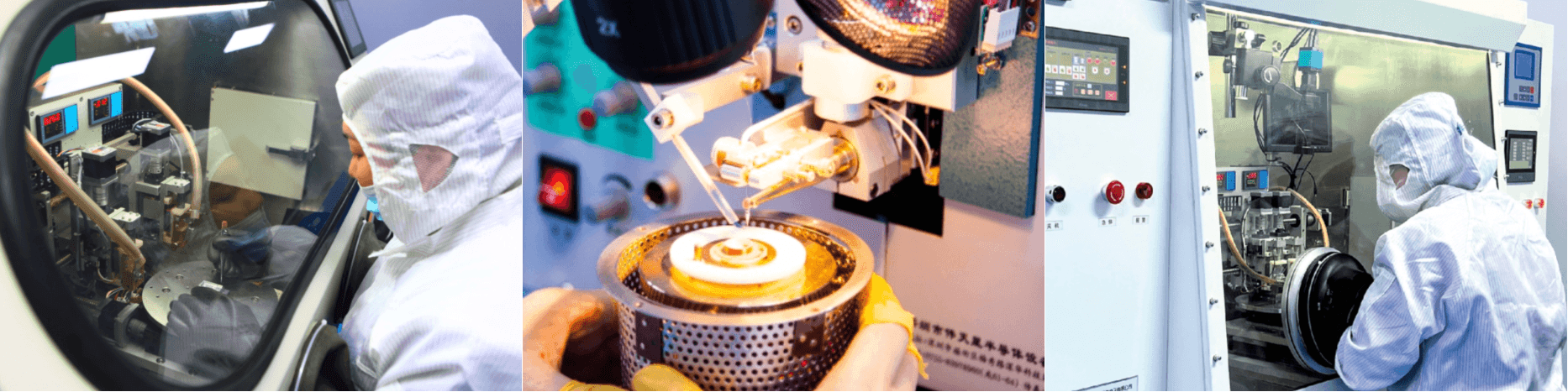
At GuideNav, we’ve supported dozens of LRF stabilization projects across ground platforms, electro-optical payloads, and gimbal-mounted systems. Whether your integration requires the compact form factor of a tactical MEMS IMU or the ultra-stable performance of a FOG gyroscope, we can help you select the right fit—technically and operationally.
Our product line spans from cost-efficient MEMS to tactical-grade FOG with proven performance in harsh, vibration-intensive environments. We also offer full technical documentation, interface support, and customization options for defense and industrial applications.