When your mission-critical platform relies on precise navigation, even the smallest gyroscope error can escalate into system-wide failure. Improper calibration, unnoticed signal drift, or aging optics in your FOG can compromise everything from UAV flight stability to submarine heading control. The good news? With proper understanding and preventive measures, your FOG can provide unmatched reliability for years.
In practical deployments, sustaining the precision and stability of a Fiber Optic Gyroscopes (FOG) requires more than advanced sensor design—it demands a calibrated system framework that includes thermal compensation, mechanical isolation, and lifecycle-aware maintenance.
Let’s break down what really determines your FOG’s longevity and how to optimize its lifecycle.
Table of contents
How Long Can Your FOG Really Last?
As someone who’s spent over a decade designing FOG systems for defense and aerospace, I can tell you this: a well-built Fiber Optic Gyroscope isn’t just accurate—it’s built to endure.
But how long is “long”? That depends. Let’s break it down.
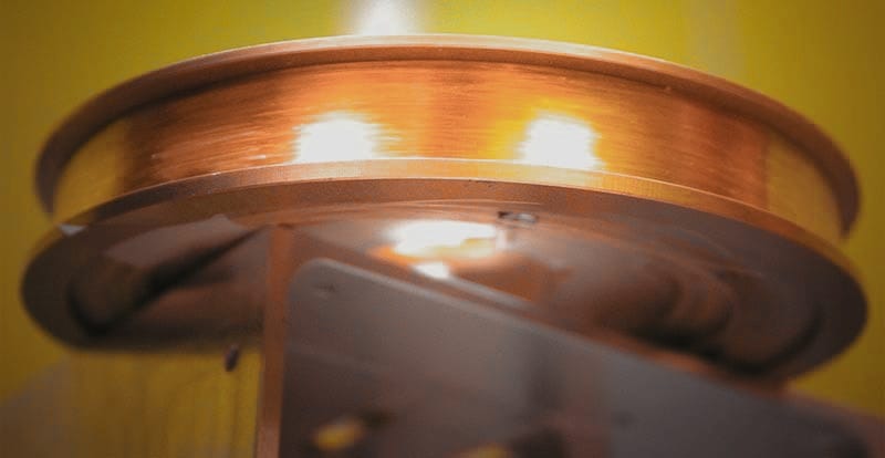
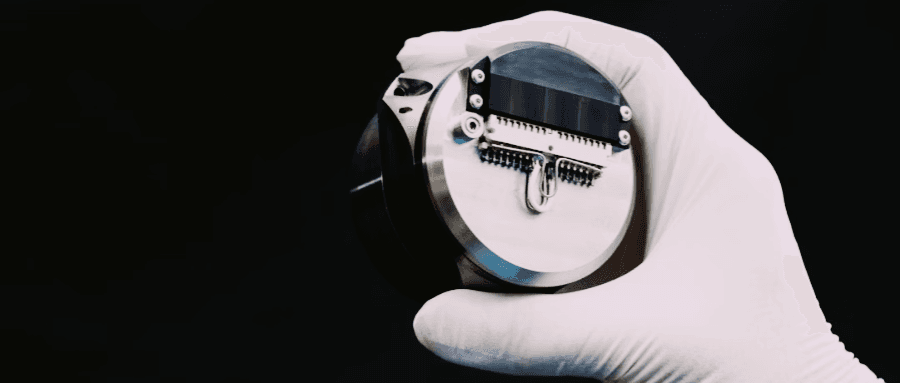
At the core, FOGs have no moving parts. They use light—traveling through coils of optical fiber—to detect rotation. No friction. No mechanical wear. This alone gives them a massive edge over mechanical or MEMS gyros in terms of reliability.
In real deployments, I’ve seen top-tier FOGs operate flawlessly for 10+ years with bias drift still under 0.01°/hr. That’s in applications like:
- Submarine navigation under high pressure
- Long-endurance UAVs flying through extreme temperature swings
- Missile systems enduring high-G shocks
Why do they last so long?
- No moving parts = no mechanical fatigue
- Thermal compensation = stability across environments
- Shock-resistant coil packaging = resilience in vibration-heavy scenarios
Military-grade units are often rated at MTBF > 150,000 hours—and that’s not just a lab number. In the field, with proper integration and thermal shielding, these gyros just keep going.
If you’re using a properly integrated FOG, expect a lifespan counted in years, not months—and with accuracy that stays locked in far longer than most alternatives.
Calibration: How Often and Why Should You Do It?
Even the most precise gyroscope will drift—not because it’s broken, but because the world around it changes.
That’s something I’ve explained to countless system integrators over the years. Temperature shifts, connector wear, and long-term electronics aging may not harm your FOG’s optics, but they do shift the data. And when you’re relying on that data for navigation, guidance, or targeting—“almost right” isn’t good enough.
So why calibrate a FOG?
Because it’s how you realign your system to reality. Not every drift is visible in a snapshot—but over time, bias and scale errors can silently degrade your accuracy.
Here’s what a typical FOG calibration involves:
- Bias modeling (to remove zero-offset drift)
- Scale factor adjustment (for rotational accuracy)
- Axis alignment verification (especially important in 6-DOF systems)
- Environmental correction (based on thermal behavior)
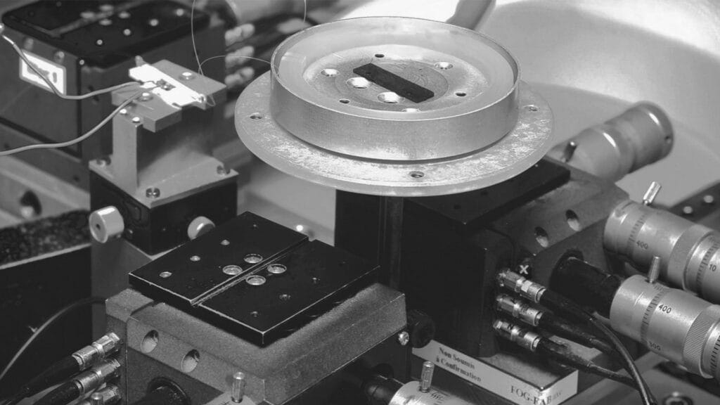
We often perform this on a precision turntable, or with GNSS/FOG fusion-based drift correction for field recalibration.
Suggested calibration frequency:
| Application | Calibration Interval |
|---|---|
| UAV navigation | 12–24 months |
| Tactical-grade land systems | 6–12 months |
| High-impact environments | Before each deployment |
Remember: calibration isn’t maintenance—it’s risk management. And in navigation, uncalibrated precision is just another form of error.
Maintenance Made Simple: What Do You Need to Know?
One of FOG’s biggest advantages is simplicity: no moving parts means fewer failure points. But that doesn’t mean you can ignore system-level maintenance.
In my diagnostics work, I’ve seen failures traced back to minor oversights—loose connectors, power fluctuations, or unnoticed moisture ingress.
Routine FOG maintenance should include:
✅ Visual check of connectors & seals
✅ Power line integrity tests
✅ Internal bias monitoring (via firmware or logs)
✅ Review of noise levels & thermal response curves
Well-integrated FOG systems also include diagnostic features like bias stability logging, laser aging prediction, or coil signal attenuation monitoring. When these tools are in place, predictive maintenance becomes feasible, and unexpected downtime can be effectively eliminated.
What Can Go Wrong? Understanding FOG Failure Modes and Prevention
Despite their durability, FOGs aren’t immune to damage. But most failure cases I’ve seen are preventable—if the integrator understands where the weak points lie.
Here are the top causes of failure we encounter:
| Failure Mode | Typical Cause | Observable Symptoms | Prevention Strategy |
|---|---|---|---|
| Signal degradation | Laser diode aging, photodetector wear | Gradual drift increase, lower signal-to-noise | Monitor output voltage and laser drive current trends |
| Fiber coil deformation | Excessive shock, improper mounting | Sudden bias jumps, complete signal loss | Use shock-damped mounts; follow vibration specs |
| Connector fatigue | Repeated thermal cycling or vibration | Intermittent signal dropouts, EMI artifacts | Locking connectors, cable strain relief |
| Moisture ingress | Seal failure in humid/deep-sea environments | Bias instability, internal corrosion | IP67+ enclosures, desiccants, potting compound |
| Power ripple damage | Inadequate power conditioning | Reset loops, unstable readings | Use EMI-filtered and regulated DC power input |
| Temperature-induced drift | Poor thermal compensation or insulation | Bias changes with temp, poor repeatability | Use FOGs with integrated thermal modeling |
| Ground loop interference | Improper grounding in multi-system platforms | Noise spikes, erratic output under load | Follow star-grounding principles, shield cabling |
| Electronics degradation | Aging ADCs or amplifiers on control board | Increased ARW, jitter in data stream | Monitor long-term Allan variance trend, replace PCB |
| Over-voltage / ESD damage | Inadequate protection during installation | Total signal failure, non-recoverable state | Add TVS diodes, ESD-safe handling protocols |
Why the Right FOG Partner Matters?
Choosing a Fiber Optic Gyroscope isn’t just about specs—it’s about system fit, mission demands, and long-term reliability. Factors like bias stability, shock resistance, interface type, and environmental sealing all play a role in real-world performance.
At GuideNav, we help you make those decisions with confidence. From tactical-grade units for UAVs to high-precision models for strategic navigation, our solutions are tailored to your platform—not the other way around.
We also go beyond hardware:
- Custom tuning and interface support
- Structural reinforcement for extreme environments
- Tailored designs for non-conventional deployment scenarios
- Flexible OEM or white-label integration
When accuracy is mission-critical, having the right sensor isn’t enough—you need the right partner. That’s where we come in.